6517B-900-01 Rev. A / Jun 2008 Return to Section Topics 4-3
Model 6517B Electrometer User’s Manual Section 4: Measurement Options
Introduction
This section describes the details of taking measurements. Configuration options, triggers, reading
storage, and scanning are just a few of the topics discussed. You will find this information useful
whether operating the Model 6517B from the front panel or IEEE-488 bus.
Multiple displays
Each measurement function and some operations provide multiple displays by using the bottom
line of the front panel. These multiple displays provide multiple type measurements, show a
reading in a different form, or give additional information about the reading.
Multiple displays are summarized in this
section. All the multiple displays are shown in Table 4-1.
The NE
XT and PREV (previous) DISPLAY keys scroll through the multiple displays for the
selected function or operation. The multiple display mode can be cancelled by pressing and
holding in either key.
Table 4-1
Multiple displays by function
Function Next display
All Time, day, and date
Bar graph
Zero-centered bar graph
Maximum and minimum values
Relative and actual values
Calculated and actual values
Limits bar graph
Relative humidity and external temperature
Change from calibration temperature
Ohms (R) Source (V) and measure (I) values
Buffer Relative humidity and external temperature,
V-Source value, maximum reading,
minimum reading, average reading,
standard deviation, and print buffer data
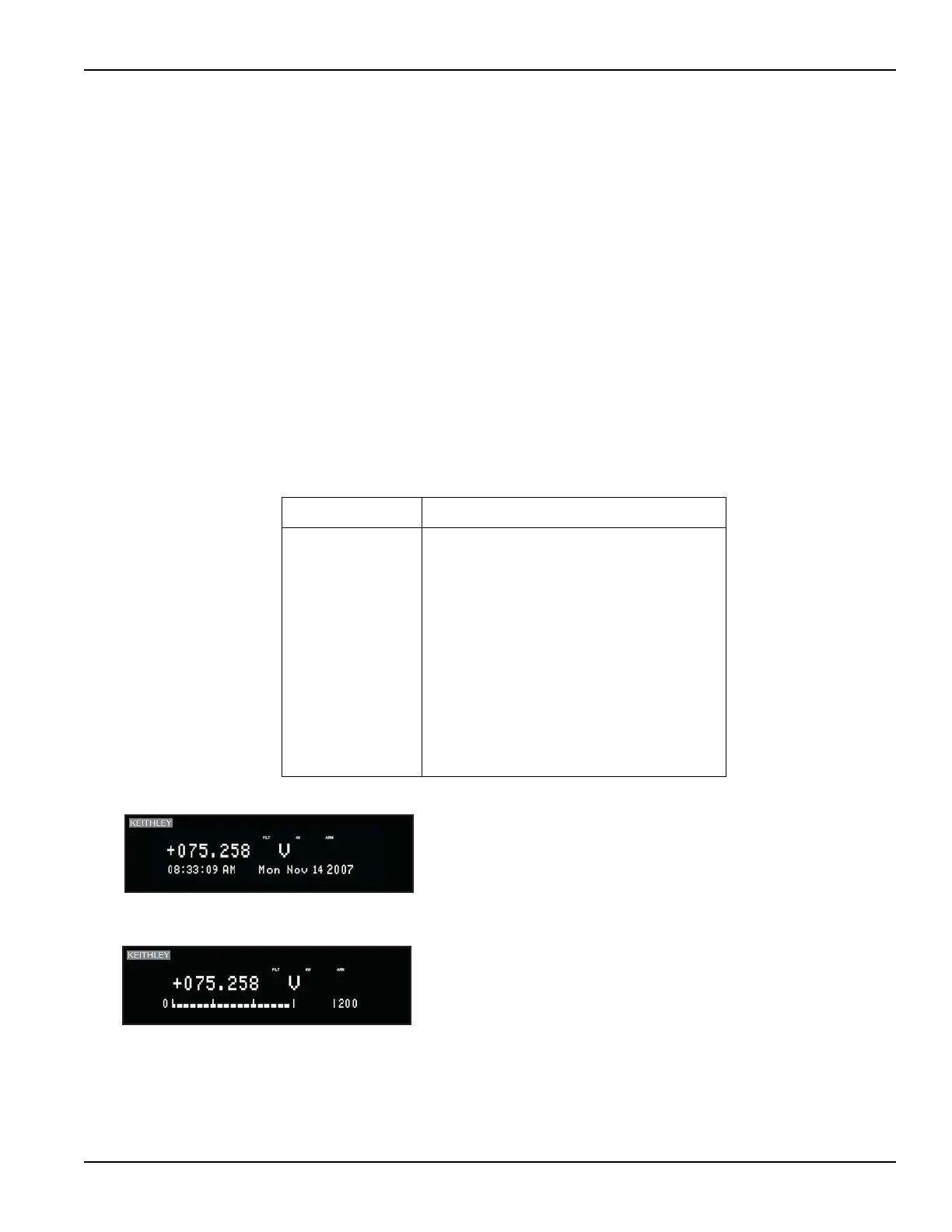
6517B ELECTROMETER/HIGH RESISTANCE METER
Time, day, and date: This display provides the time, day of
week, and the date. The time, date, and format (12-hour or 24-
hour) are set from the CLOCK option of the GENERAL MENU
(see Menus for more information).
6517B ELECTROMETER/HIGH RESISTANCE METER
Bar graph: The bar graph is a graphical representation of the
reading with zero at the left end. Each full segment of the bar
represents approximately 4% of the range limit.
Test Equipment Depot - 800.517.8431 - 99 Washington Street Melrose, MA 02176
TestEquipmentDepot.com