6517B-900-01 Rev. A / Jun 2008 Return to Section Topics 4-5
Model 6517B Electrometer User’s Manual Section 4: Measurement Options
Menus
There are two basic menu structures used by the Model 6517B: The main menu and the CONFIG
menus. The main menu accesses items for which there are no dedicated keys. The CONFIG
menus are used to configure measurement functions and other instrument operations.
Table 4-2 su
mmarizes main menu selections. Table 4-3 and Table 4-4 show configuration settings
for the measurement functions an
d instrument operations.
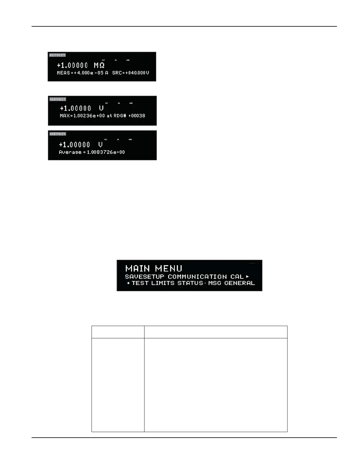
Figure 4-1
Main menu display
Table 4-2
Main menu summary
Option Description
SAVESETUP Save and restore setups stored in memory, set power-on
defaults, and return unit to default conditions.
COMMUNICATION Select and configure interface (GPIB or RS-232).
CAL Calibrate the Model 6517B, perform offset adjustments, and
check calibration date.
TEST Perform self-tests (see Reference Manual).
LIMITS Configure unit to perform limit tests.
STATUS-MSG Enable/disable status message mode.
GENERAL Control output lines of digital output port, check serial
number of unit and firmware revision levels, control
line-sync, limit control and data stamp, configure
timestamp, set reading display, and set real-time clock.
6517B ELECTROMETER/HIGH RESISTANCE METER
Measure/source: This display is used to display the measured
current and the V-Source level for ohms measurements.
6517B ELECTROMETER/HIGH RESISTANCE METER
6517B ELECTROMETER/HIGH RESISTANCE METER
Buffer: When in RECALL, there are seven displays for buffer
readings:
Relative humidity (RH) and temperature (ET)
V-Source value
Maximum reading (shown at left)
Minimum reading
Average reading (shown at left)
Standard deviation
Print buffer data
Test Equipment Depot - 800.517.8431 - 99 Washington Street Melrose, MA 02176
TestEquipmentDepot.com