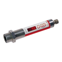
The device is a pyrometer, specifically the CellaTemp PK/PKF/PKL xx series, designed for non-contact temperature measurements. It detects infrared energy radiated by hot objects and converts it into an electrical switch signal. This method offers several advantages, including cost-effectiveness (requiring a single investment without follow-up costs for consumables like thermocouples), the ability to measure moving or hard-to-reach objects, surface-treated or voltage-carrying objects, sticky materials (such as dough or aggressive chemicals), and applications requiring fast response times. The pyrometer is housed in a rugged stainless steel casing, making it suitable for harsh industrial environments, and is splash-proof according to IP65 (DIN 40050). It features an analog output and a switch contact that can be configured as an opener or closer.
Function Description:
The pyrometer measures temperature without contact. The infrared sensor is equipped with an analog output and an open collector output. The instrument's display panel shows the measured temperature. It generates two output signals based on the configured function: OUT1 for switching threshold and OUT2 for analog output (0/4...20mA).
Switching Threshold (OUT1):
OUT1 changes its switching status when the configured upper and lower thresholds are exceeded. The temperature threshold can be defined in °C or °F. When adjusting the upper threshold, the lower threshold will change accordingly, and the span remains the same. If the lower threshold is set to a value where the span cannot be maintained (as its minimum value), the upper threshold is kept at its minimum value. The minimum distance between upper and lower thresholds is 2 K. Switching functions can be normally open or normally closed. An upper threshold delay and lower threshold delay can be configured (up to 10 seconds in steps of 0.1 seconds) to ensure that the output impulse is correctly identified and lengthened by a downstream control system.
Analog Output (OUT2):
The pyrometer is equipped with an analog output OUT2 0/4...20 mA. The maximum load is 500 Ω. The output current is linear to the measured temperature. The measuring range can be set to °C or °F using parameters for the beginning and end of the range. The output can be switched between 0-20 mA and 4-20 mA. The beginning of the scale can be entered in °C or °F, and the end of the scale changes accordingly, maintaining the range. If the range is increased so far that the range cannot be adhered to, the range is kept at its maximum. If the range is reduced again, the range is immediately reduced. The minimum span is given in the technical data of the respective device.
Emissivity of Materials:
The pyrometer measures thermal energy (infrared radiation) emitted by an object. The ability to radiate heat depends on the type of material and its surface properties. The emissivity coefficient is a correction factor for the radiation properties of the measured object (10...110%). It can be determined by contact measurements (using a thermocouple) or by applying a matte black color (94% emissivity) as a reference. The spectral emissivity coefficient is not an exact material constant and depends on surface properties.
IO-Link:
The device features an IO-Link communication interface, requiring an IO-Link-capable module (IO-Link master). This interface allows direct access to process and diagnostic data and facilitates device parameterization during operation. IODDs (IO-Link Device Descriptions) for configuration, process data setup, diagnostic functions, and parameter addresses are available on the manufacturer's website. A 3-wire cable port Class A (Type A) must be used for IO-Link operation.
Important Technical Specifications (General):
- Load: max. 500 Ω
- Switching output OUT1: Open Collector output 24 V, ≤ 150 mA, Schaltpunkt [°C]/Rückschaltpunkt [°C], Hysterese ≥ 2 K, Ein-/Ausschaltverzögerung, NC/NO
- Ambient temperature: 0 - 65 °C
- IO-Link revision: V1.1, downward compatible to V1.01
- SIO mode: yes, supported
- Transmission rate: COM2 (38.400 Baud)
- Storage temperature: -20 - 80 °C
- Permissible humidity: 95 % r.H. max. (non condensing)
- Power requirement: 24 V DC +10 % / -20 % Ripple ≤ 200 mV
- Housing material: Stainless steel
- Weight: approx. 0.4 kg
- Connectivity: 5-pin connection M12 (A coded)
- Protection: IP 65 according to DIN 40050 with screwed plug
- Configuration parameters: Emissivity ε 10 - 110 %, Smoothing function t98 0,1 - 999,9 s, Peak hold function 0,1 - 999,9 s
Device-Specific Technical Data (Examples):
PK 11 AF 1/PK 18 AF 1/PK 18 AF 2:**
- Temperature range: PK 11 AF 1: 0 - 1000 °C / PK 18 AF 1: 0 - 500 °C / PK 18 AF 2: 0 - 400 °C
- Sensor: Thermopile
- Spectral sensitivity: 8 - 14 µm
- Focus distance: 300 mm
- Target spot diameter: 11 mm
- Analogue output OUT2: 0(4) - 20 mA linear, switchable, scalable (≥ 50 K)
- Resolution current output: 0.2 K + 0.03 % of selected range
- Resolution temp. reading: 0.1 K < 200 °C, 1 K ≥ 200 °C
- Response time t90: ≤ 60 ms
- Repeatability: 1 K
- Measurement uncertainty: 0.75 % of temp. reading [°C] plus 2.0 K
- Temperature coefficient: 0.1 K/K (for T<250°C), 0.04 %/K (for T>250°C) of temp. reading / K
- Dimensions: M30 x 185 mm (without plug)
- CellaTemp PK 18 has a special resistant lens for extreme environmental conditions.
PK 21 AF 1:
- Temperature range: 250 - 1600 °C
- Sensor: InGaAs
- Spectral sensitivity: 1.0 - 1.7 µm
- Focus distance: 1500 mm
- Target spot diameter: 10 mm
- Response time t90: ≤ 2 ms (for T > 600 °C)
- Measurement uncertainty: 0.3% of temp. reading [°C] plus 2.5 K (at ɛ =1.0 and Ta = 23 °C)
PKF 26 AF 1 (Fiber Optic):
- Temperature range: 300 - 1600 °C
- Sensor: InGaAs
- Spectral sensitivity: 1.0 - 1.7 µm
- Focus distance: 200 mm ... ∞ (adjustable)
- Distance ratio: 180:1 (measuring head PA 41.01)
- Ambient temperature measuring head: fiber optic metal 0 - 250 °C
- Dimensions: M30 x 200 mm (electronics without plug), M30 x 67...86 mm (fiber optic measuring head)
Usage Features:
- Operating Controls and Display: The pyrometer features a 4-digit display, 3 control keys (Enter, Up, Down), and 3 LEDs. The LEDs indicate switching output, temperature in °F, and temperature in °C. The alphanumeric display shows temperature value, parameters, configuration, and overload at the switching output.
- Menu Navigation: Parameters can be selected and confirmed using the "Enter" key. Configuration parameters are adjusted with the "Up" and "Down" keys.
- Process Value Display: The display shows the current temperature value. It can be locked/unlocked, and parameters can be viewed.
- Keylock: The instrument has a keylock feature. It can be activated/deactivated by pressing the "Up" and "Down" keys simultaneously for 10 seconds. "Loc" or "uLoc" will be displayed for 1 second. Briefly pressing both keys exits the current layer (ESC function). "C.Loc" indicates temporary locking via parameter setting software, while "S.Loc" indicates permanent software locking.
- Test Function: An integrated diagnostics function checks signal processing, switching output, and analog output. It can be activated via control keys or a static signal (10-34 V) on Pin 5.
- Damping Function: Smooths temperature fluctuations when the target temperature is erratic, stabilizing the measuring signal. The damping time constant can be set from 0.1 to 999.9 seconds.
- Peak Hold Function: Captures and saves the maximum temperature sampled during a defined hold time (0.1 to 999.9 seconds). This is useful for moving targets to avoid temperature drops.
- Reset to Factory Settings: All parameters can be reset to factory settings through the "Advanced Functions" menu. After a reset, the emissivity coefficient must be reconfigured.
- Operation: After connecting the supply voltage, the pyrometer initializes and performs a self-diagnosis. It is ready for operation after approximately 0.5 seconds. Configuration parameters for OUT1, OUT2, and Advanced Features can be displayed.
- Error Indications: The device provides various error indications, such as overload output (LED 1 flashes at 4 Hz), overtemperature (LED 1 flashes at 4 Hz, measurement at 0.5 Hz), incorrect connection of supply voltage (LED 1 flashes at 2 Hz), supply voltage ≤ approx. 16 V (LED, switching output, and analog output deactivated), temperature below lower threshold (display shows "UL"), and temperature above upper threshold (display shows "OL").
- Setup: The pyrometer uses infrared radiation for non-contact temperature measurements. It is crucial to configure the emissivity coefficient correctly to obtain accurate results. The emissivity coefficient can be set after connecting the supply voltage or by resetting parameters to factory settings.
- Aligning and Focusing the Fiber Optic Head: For fiber optic models, the fiber optic head must be aligned on the target. A laser pointer can be used for this purpose. Focal adjustment involves loosening a socket screw and shifting the internal body of the tube. The sensing head should be focused so that the spot light is a sharp round laser spot in the target area.
- Laser Safety: Laser pointers (Class 2 red light laser, 630-670 nm, max. 1.0 mW) are used for alignment. Safety precautions include deactivating the laser immediately after alignment, never looking directly into the beam, not leaving the instrument unattended when activated, not pointing the laser at any person, and avoiding reflections from shiny surfaces.
Maintenance Features:
- Cleaning the Pyrometer Lens: A false temperature reading can occur if the lens is dirty. The lens should be cleaned periodically with a soft, clean, lint-free cloth and a very mild liquid detergent. Rinse with clear water and gently pat dry. Avoid scratching the lens.
Shipping, Packaging, and Disposal:
- Inspection after shipping: Unpack and inspect the entire shipment immediately. Report any visible signs of damage to the carrier. If concealed damage is found, report it to the shipper or freight carrier.
- Packaging: The packages are made of carefully selected, environmentally compatible materials and are recyclable.
- Disposal of old devices: Old electrical and electronic devices should be returned for disposal to the manufacturer or disposed of properly by the user. Keller HCW is not responsible for improper disposal.