EasyManua.ls Logo

Kelley aFX - Wiring Diagram

Kelley aFX
21 pages
Print Icon
To Next Page IconTo Next Page
To Previous Page IconTo Previous Page
Loading...

 





 



        
        




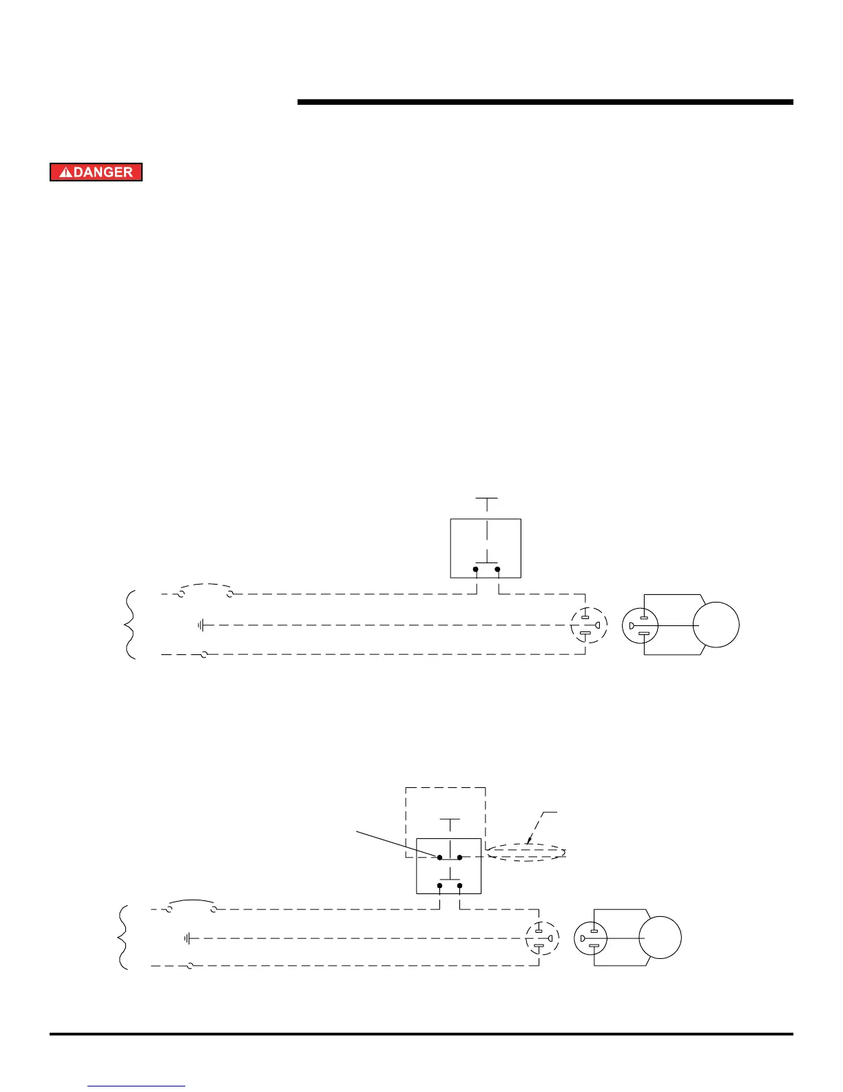
Optional Blue Contact Block
(Normally Closed)
Field Installed (Low Voltage Only)
See Supplied Mfg. Instructions
Control
Station
Control
Station
Optional connection to restraint
Star4 LA terminals C and 17.
For Star4 module with 403 controller
use 21 and 22
To:
Auto chock terminal block
terminals no. 5 and no. 24
Pit Wall
Receptacle
NEMA 5-15R
(By Others)
Pit Wall
Receptacle
NEMA 5-15R
(By Others)
1 Phase 120V
50/60 Hz
1 Phase 120V
50/60 Hz
BLK
WHT
GRN
Motor
BLK
WHT
GRN
Motor
Circuit Breaker
(By Others)
20 AMP MAX
Circuit Breaker
(By Others)
20 AMP MAX
Line
Line
Grn
Grn
Neutral
Neutral
120V
1 Phase
50/60 Hz
120V
1 Phase
50/60 Hz
120V, Single Phase, 50/60 Hz
Optional Dual Contact
120V, Single Phase, 50/60 Hz
Single Contact


Related product manuals