Do you have a question about the Kenmore 111.72695120 and is the answer not in the manual?
Safety guidelines for servicing the refrigerator to prevent accidents and ensure safe operation.
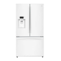
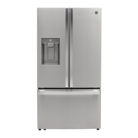
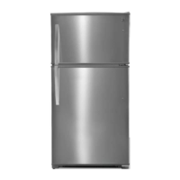
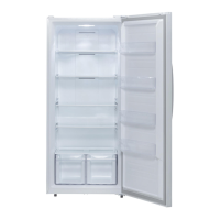
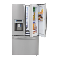
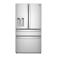
Overview of the refrigerator's external components and included parts.
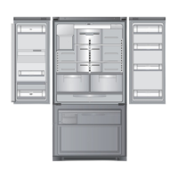
Detailed view and labeling of the refrigerator's internal compartments and features.
Identification and location of various sensors and internal components.
Identification of components located in the refrigerator's machine room.
Diagram illustrating the path of cold air circulation within the refrigerator.
Diagram and specifications for the refrigerator's water supply system.
Diagram showing refrigerant flow and connection points for service.
Comprehensive wiring diagram of the main control board and connected components.
Continuation of the total wiring diagram, detailing more connections.
Detailed wiring schematic specifically for the icemaker system.
Diagrams showing PCB interconnections for user interface controls.
Details on the operation of dispenser, DV, and icemaker heaters related to wiring.
Wiring and operational data for damper and step valve control.
Wiring details for the inner control panel and sensor connections.
Guide to operating the refrigerator's dispenser control panel buttons and displays.
Guide to operating the refrigerator's main inner control panel buttons.
Further details on inner control panel functions like Wi-Fi and air filter.
Instructions for accessing and using service modes like Forced Defrost and Comp ON.
Fine-tuning sensor temperature adjustments via the inner control panel.
Procedures for entering service mode and interpreting error codes for diagnosis.
Steps to manually initiate the defrost cycle for troubleshooting.
Steps to manually activate the compressor for testing or refrigerant charging.
Guide for testing and diagnosing the refrigerator's Wi-Fi connectivity.
Table detailing compressor, fan, and damper behavior under various conditions.
Explanation of how the DC fan motor operates and its error detection logic.
Information on how the defrost mode initiates and returns to normal operation.
Explanation of the fill tube heater's function and activation triggers.
Operation and control of the icemaker, including temperature and water supply.
Procedures for powering off, testing, and troubleshooting the icemaker.
Control and error behavior for the temperature-controlled pantry drawer.
Guidelines for using the dispenser lever to prevent component damage.
Explanation of the buzzer sounds and alarm conditions for user feedback.
Procedure for adjusting refrigerator temperature by modifying sensor resistance.
Troubleshooting flowchart for refrigerators with no power or lights.
Troubleshooting flowchart for refrigerators failing to cool food properly.
Troubleshooting flowchart to diagnose and resolve ice buildup on the freezer louver.
Steps to check and repair issues with the freezer compartment lighting.
Steps to check and repair issues with the pantry compartment lighting.
Steps to check and repair issues with the refrigerator compartment lighting.
Troubleshooting flowchart for general refrigeration cooling failures.
Troubleshooting steps to diagnose and fix excessive condensation inside the refrigerator.
Flowchart to identify and resolve abnormal noise from the compressor.
Guide to diagnosing and addressing sounds related to refrigerant flow.
Troubleshooting steps for identifying and resolving fan noise issues.
Flowchart to diagnose and eliminate noise originating from refrigerant pipes.
Troubleshooting steps for the door alarm that triggers with the door closed.
Step-by-step guide for removing and installing the water filter holder assembly.
Instructions for disassembling and reassembling the water tank and vegetable crisper cover.
Procedure for disassembling and assembling the ice maker's water supply tubing.
Steps to remove and access the refrigerator's icemaker unit.
Instructions for disassembling and reassembling the fixture geared motor.
Guide to removing and replacing the pantry drawer cover and multi-duct assembly.
Steps to remove refrigerator/pantry sensors and dampers from the multi-duct cover.
Procedure for removing the defrost sensor and heater from the evaporator assembly.
Instructions for disassembling the damper cover and insulation damp assembly.
Steps to remove the defrost sensor from the ice maker evaporator assembly.
Procedure for replacing the defrost heater in the ice maker evaporator assembly.
Instructions for disassembling and reassembling the main control panel PCB.
Guide for disassembling and reassembling the supporter for the draw rail.
Steps for disassembling and assembling the freezer louver.
Instructions for removing the freezer sensor, F fan, and fan motor.
Procedure for removing the freezer defrost sensor and heater from the evaporator.
Steps to remove and replace the condenser fan motor in the machine room.
Guide for disassembling and replacing door switches in all compartments.
Instructions for removing the front control panel and dispenser assembly.
Steps for disassembling and reassembling the box dispenser unit.
Guide for disassembling and reassembling the lever mechanism of the dispenser.
Instructions for disassembling and reassembling the mullion bar, including heater.
Steps to remove and replace interior lamps in the freezer, middle, and refrigerator compartments.
Procedure for safely removing and replacing the Wi-Fi module.
| Brand | Kenmore |
|---|---|
| Model Number | 111.72695120 |
| Type | Top Freezer Refrigerator |
| Color | White |
| Defrost Type | Frost-Free |
| Door Swing | Right |