ET'S KEEP GOING...IT'S GETTING EASIER, WE HOPE.
7
NOW WE'RE GETrlNG INTO
THE ACTUAL INSTALLATION.
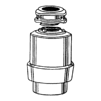
SEPARATE THE PARTS IN
THE MOUNTING ASSEMBLY.
Lower
Wrenchette
First, remove the mounting assembly
from the lower mounting ring, Holding
the mounting assembly with one hand,
insert your wrenchette or screwdriver
into one of the lugs of the lower moun-
ting ring and turn it to the left
(counterclockwise) with your other
hand.
MountingRing /_
._ing
Now, use a screwdriver to pry off the
snap ring.
Screw
Then loosen the screws on the moun-
ting assembly until they are just level
with the surface of the mounting ring.
Groove
Sinl_Sleeve
_ Mounting
• t "_..___--3"-_Riog
The assembly will now come apart. Set
it aside and move to the next step.
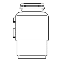
NEXT, LET'S ATTACH THE
UPPER MOUNTING
ASSEMBLY.
First, working from under the sink, slip the
fiber gasket and next the metal back-up
ring (flat side Up) up and over the sink
sleeve,
3.
Holdthe fiber gasket and metal back- up
ring in place with one hand and place
the mounting ring with its three screws onto
the sink sleeve.
Now, push the fiber gasket, metal back-up
ring and the mounting ring further up on the
sink sleeve. Slide the snap dng onto the sink
sleeve until it pops into place in the groove
)n the sleeve.
Tighten the three mounting screws with
your screwdriver until the whole mounting
assembly is seated evenly and tightly
against the sink.
8
APPLY PUTTY TO THE
SINK SLEEVE.
A.
Make a fat snake of "plumber's"
putty by rolling it between your
hands.
B.
Apply this roll under the rim of the
sink sleeve.
Then, place the sink sleeve into the
sink drain hole and push down
gently but firmly to make sure it sits
evenly in the putty.
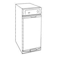
0 TURN YOUR NEW
DISPOSER UPSIDE
DOWN AND REMOVE
THE ELECTRICAL
PLATE FROM THE DISPOSER SO
YOU CAN SEE THE WIRING AND
THE GROUND SCREW. THE BOTTOM
OF YOUR DISPOSER WILL LOOK
LIKE THE ONES SHOWN IN 'A' OR 'B'.
{Start here if you are replacing a disposer withthe same mounlJng.)
Remove the electrical plate from the bottom of the disposer and pull out the
black and white electrical wires. The green ground screw is also under this
plate.
A,
BLACK AHO
GREEN GROUND wHrTE WIRES
So
RESEt
GREEN GROUND
CABLE CLAMp
BLACK AND