f" \
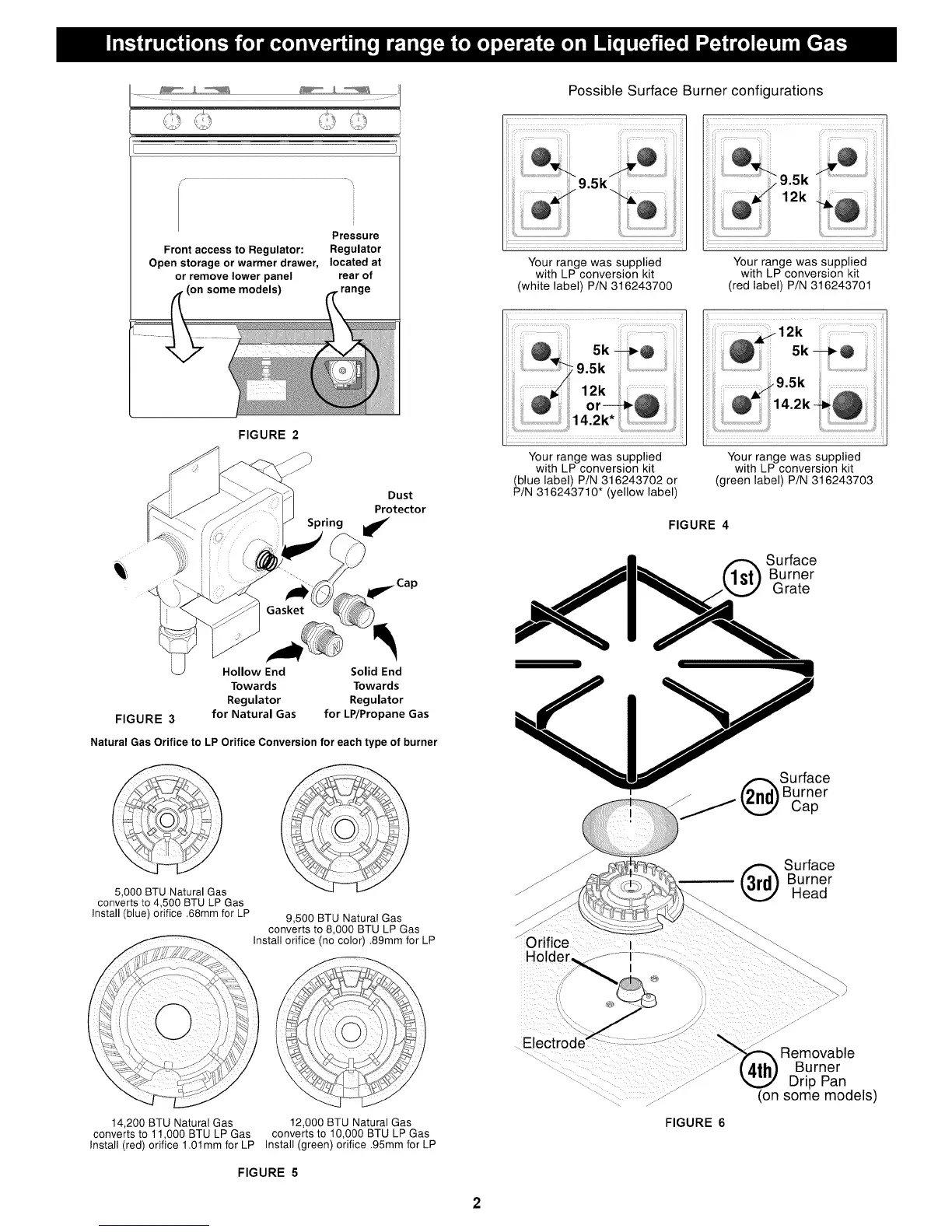
Pressure
Front access to Regulator: Regulator
Open storage or warmer drawer, located at
or remove tower panel rear of
_ models) _,_range
FIGURE 2
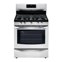
FIGURE 3
Hollow End
Towards
Regulator
for Natural Gas
Dust
Protector
Spring _
__ il_ Ca p
Solid End
Towards
Regulator
for LP/Propane Gas
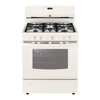
Natural Gas Orifice to LP Orifice Conversion for each type of burner
5,000 BTU Natural Gas
converts to 4,500 BTU LP Gas
Install (blue) orifice .68mm for LP 9,500 BTU Natural Gas
converts to 8,000 BTU LP Gas
Install orifice (no color) .89mm for LP
14,200 BTU Natural Gas
converts to 1! ,000 BTU LP Gas
Install (red) orifice 1.01mm for LP
!2,000 BTU Natural Gas
converts to 10,000 BTU LP Gas
Install (green) orifice .95mm for LP
FIGURE 5
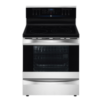
Possible Surface Burner configurations
Your range was supplied
with LP conversion kit
(white label) P/N 316243700
i :::ii i ii¸¸¸il! ii J
Your range was supplied
with LP conversion kit
(red label) P/N 316243701
12k
Your range was supplied
with LP conversion kit
(blue label) P/N 316243702 or
P/N 316243710* (yellow label)
Your range was supplied
with LP conversion kit
(green label) P/N 316243703
FIGURE 4
• _ Surface
Burner
*e
Surface
Burner
Cap
_J
Orifice
Hoh
(_ Surface
Burner
Head
El
FIGURE 6
Removable
Burner
Drip Pan
(on some models)