Do you have a question about the Kenmore 795.51022.001 and is the answer not in the manual?
Covers electrical parameters, no-load performance, and refrigeration system specifications.
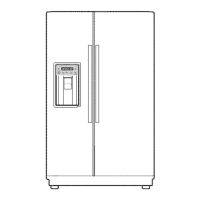
Details installation clearance requirements and lists replacement parts.
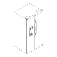
Illustrates the air circulation path within the refrigerator unit.
Step-by-step guide to align refrigerator doors for proper fit and function.
Guide on how to install the water filter and reset the filter indicator.
Details on how to remove and adjust refrigerator shelves for space optimization.
Procedure for removing the shelf from the freezer compartment.
Method to control the amount of water supplied to the icemaker for optimal ice production.
Covers procedures for removing and replacing refrigerator doors and handles.
Instructions for disassembling components like switch lamp, fan grille, icemaker, and water valve.
Guide on assembling water valve tubes, fan motor, drip tray, and dispenser unit.
Overview of the refrigerator's control panel buttons, indicators, and their functions.
Explains display functions, modes like Demonstration, Lock, Filter status, and ULTRA ICE.
Details operations for ULTRA ICE, variable fan control, cooling fan, and door opening alarm.
Explains test modes, sequential operations, and failure diagnosis functions for the MICOM system.
Explanation of the refrigerator's power supply circuit, including rectifier, transformer, and feedback circuits.
Details the oscillation circuit for MICOM synchronization and the reset circuit for component restarts.
Covers circuits for load driving, dispenser operation, and door opening sensing.
Explains temperature sensing circuits and circuits for test and diagnostic switches.
Details the stepping motor operation circuit and the fan motor driving circuit.
Explains the operational cycle of the ice maker from power input to ice ejection.
Details on how the dispenser functions for water, cubed ice, and crushed ice.
Guides through common refrigerator faults, their causes, and check points.
Guides for diagnosing abnormal freezer, refrigerator, defrost, and temperature sensor errors.
Guides for diagnosing abnormal fan errors and poor/overcooling performance in sections.
Guides for diagnosing faults in ice cube, crush, dispensing modes, and ice maker unit.
| Brand | Kenmore |
|---|---|
| Model Number | 795.51022.001 |
| Type | French Door |
| Width | 35.75 inches |
| Ice Maker | Yes |
| Water Dispenser | Yes |
| Energy Star Certified | Yes |
| Color | Stainless Steel |
| Height | 69.75 inches |