Do you have a question about the Kenmore 796.40019 and is the answer not in the manual?
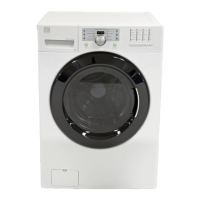
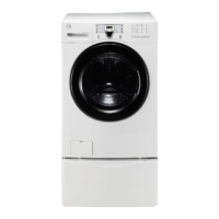
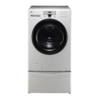
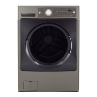
Lists key features of the washing machine, such as capacity and drive system.
Explains the intelligent washing time adjustment process based on load and temperature.
Describes how the water level is managed by a pressure sensor.
Details the operation and locking mechanisms of the washing machine door.
Lists included accessories with the washing machine, such as hoses and wrench.
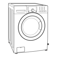
Outlines the steps for proper installation and leveling of the appliance.
Instructions for connecting the water inlet hose correctly to prevent leaks.
Guidelines for connecting the drain hose to prevent issues like kinking or submerging.
Instructions for safely connecting the power plug to a wall outlet.
Explains the functions of each button and indicator on the washing machine's control panel.
Details the various optional functions available for wash cycles, such as Stain Treat and Delay Start.
Explains how to select wash settings like temperature, spin speed, and soil level.
Provides a guide to different wash cycles, recommended fabric types, and settings.
Describes special functions like Stain Treat, 2nd Rinse, Auto Soak, Delay Start, Clean Washer, and Control Lock.
Explains the steps involved in various washing processes, from water supply to untangling.
Safety precautions for performing test modes on the appliance.
Instructions for entering and using the load test mode for diagnostics.
Procedure for checking water level frequency for diagnostic purposes.
Safety warnings related to troubleshooting procedures and electrical shock.
Overview of error codes displayed by the machine and their general meanings.
A summary of troubleshooting steps, including circuit diagrams and error code causes.
Step-by-step troubleshooting for specific error codes like Inlet Valve, Drain, Heating, and Locked Motor.
Troubleshooting for other issues like no power, button errors, vibration, and detergent dispensing.
Information on testing the line filter component, including circuit diagram and test points.
Details on the door lock switch assembly, its function, and testing procedures.
Information on testing the stator assembly, including windings and hall sensor.
Information on testing the pump motor assembly, including its function and resistance.
Information on testing the inlet valve assembly and its resistance values.
Information on testing the heater assembly and its resistance values.
Information on testing the thermistor assembly and its resistance values at different temperatures.
Step-by-step instructions for disassembling the control panel assembly.
Step-by-step instructions for disassembling the main PCB assembly.
Step-by-step instructions for disassembling the dispenser assembly.
Instructions for disassembling the noise filter component.
Step-by-step instructions for disassembling the cabinet cover.
Step-by-step instructions for disassembling the washing machine door.
Instructions for disassembling the door lock switch assembly.
Step-by-step instructions for disassembling the pump assembly.
Step-by-step instructions for disassembling the heater assembly.
Step-by-step instructions for disassembling the thermistor.
Instructions for removing foreign objects stuck between the drum and tub.
Instructions for disassembling the motor and damper components.
Exploded view of the cabinet and control panel assembly components.
Exploded view of the drum and tub assembly components.
Exploded view of the dispenser assembly components.
| Brand | Kenmore |
|---|---|
| Model Number | 796.40019 |
| Capacity | 4.5 cu. ft. |
| Color | White |
| Energy Star Certified | Yes |
| Spin Speed | 1300 RPM |
| Steam Washer | Yes |
| Number of Temperature Settings | 5 |
| Agitator | No |
| Automatic Load Sensing | Yes |
| Delay Start | Yes |
| Deep Fill Option | Yes |
| Quick Wash Cycle | Yes |
| Voltage | 120 V |
| Frequency | 60 Hz |
| Height | 38 in. |