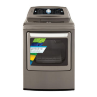
Do you have a question about the Kenmore 796.9027.900 and is the answer not in the manual?
Instructions for 4-wire and 3-wire power cord connections.
Procedure for connecting the gas supply pipe to the gas dryer.
Procedures for testing thermal cut-off and hi-limit/outlet thermostats.
Testing procedures for door switch, idler switch, and lamp holder.
Tests for electrical supply, thermistor, motor, moisture sensor, and door switch.
Tests for heater switch (electric) and gas valve (gas type).
Steps for removing the dryer's top plate and control panel assembly.
Instructions for removing the cover cabinet, tub drum, and lamp.
Procedures for dryer exhaust, filter, blower housing, air duct, and rollers.
Steps for removing the dryer's back cover.
Exploded view of the control panel and related plate assembly components.
Exploded view of the cabinet and door assembly for gas type dryers.
Exploded view of the drum and motor assembly for gas type dryers.
Exploded view of the drum and motor assembly for electric type dryers.
| Appliance Category | Dryer |
|---|---|
| Brand | Kenmore |
| Model Number | 796.9027.900 |
| Control Type | Electronic |
| Energy Star Certified | Yes |
| Color | White |
| Voltage | 240 V |
| Amperage | 30 A |
| Width | 27 inches |
| Drum Material | Stainless Steel |
| Number of Temperature Settings | 4 |
| Wrinkle Guard Option | Yes |
| Moisture Sensor | Yes |
| End of Cycle Signal | Yes |
| Lint Filter | Yes |
| Type | Electric |


