EasyManua.ls Logo

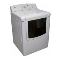
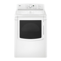
Kenmore Oasis 110.77072600 User Manual

Kenmore Oasis 110.77072600
110 pages
To Next Page IconTo Next Page
Page #1 background imageLoading...
Page #1 background image
SOURCE 110
2006
ELECTRIC & GAS DRYER
Electric Models:
110.67032600
110.67042600
110.67052600
110.67062600
110.67072600
110.67082600
110.67086600
110.67087600
110.67092600
Gas Models:
110.77032600
110.77042600
110.77052600
110.77062600
110.77072600
110.77082600
110.77086600
110.77087600
110.77092600
CONFIDENTIAL - Sears Internal Technical Reference Material
Do Not Distribute To Anyone Other Than A Sears Associate
© 2006 Sears Holding Company
Manual No: 26210206

Table of Contents

Question and Answer IconNeed help?

Do you have a question about the Kenmore Oasis 110.77072600 and is the answer not in the manual?

Kenmore Oasis 110.77072600 Specifications

General IconGeneral
BrandKenmore
ModelOasis 110.77072600
CategoryDryer
LanguageEnglish

Summary

SECTION 2 INSTALLATION INFORMATION

ELECTRICAL REQUIREMENTS

Defines the necessary electrical supply and connection types for electric models.

GAS SUPPLY REQUIREMENTS

Details requirements for connecting the gas supply line and related components.

VENTING REQUIREMENTS

Crucial safety and performance guidelines for proper dryer exhaust venting.

INSTALL VENT SYSTEM

Step-by-step instructions for installing the exhaust vent hood and ducting.

MAKE GAS CONNECTION

Instructions for safely connecting the gas supply to gas dryer models.

CONNECT VENT

Final steps for connecting the dryer vent to the exhaust outlet and ensuring proper airflow.

SECTION 4 COMPONENT ACCESS

REMOVE USER INTERFACE, MACHINE CONTROL, MOTOR CONTROL

Procedures for accessing and removing console and control board components.

REMOVE MOISTURE SENSOR

Step-by-step guide to remove the moisture sensor assembly from the dryer.

REMOVE CABINET FRONT AND DOOR SWITCH

Instructions for removing the dryer's front panel and door switch.

REMOVE DRUM LIGHT ASSEMBLY

Steps for safely removing the internal drum light assembly and bulb.

REMOVE THERMAL FUSE & OUTLET THERMISTOR

Procedures for accessing and removing the thermal fuse and outlet thermistor.

REMOVE HEATER COMPONENTS (ELECTRIC MODELS)

Guide for removing thermostats, thermal cutoff, and electric heater elements.

REMOVE GAS BURNER COMPONENTS (GAS MODELS)

Steps to access and remove high-limit thermostat, flame sensor, and gas burner assembly.

REMOVE BELT, DRUM, & ROLLERS

Procedures for removing the dryer drum, belt, and support rollers.

REMOVE BLOWER FAN ASSEMBLY

Instructions for removing the blower fan assembly, typically in single-motor models.

REMOVE BLOWER MOTOR AND FAN (DUAL MOTOR MODELS)

Steps for removing the blower motor and fan in dual-motor configurations.

SECTION 5 COMPONENT TESTING

SECTION 6 DIAGNOSTICS & TROUBLESHOOTING

SECTION 7 WIRING DIAGRAMS & STRIP CIRCUITS

Related product manuals