EasyManua.ls Logo

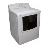
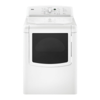
Kenmore Oasis 110.77092600 User Manual

Kenmore Oasis 110.77092600
110 pages
To Next Page IconTo Next Page
Page #1 background imageLoading...
Page #1 background image
SOURCE 110
2006
ELECTRIC & GAS DRYER
Electric Models:
110.67032600
110.67042600
110.67052600
110.67062600
110.67072600
110.67082600
110.67086600
110.67087600
110.67092600
Gas Models:
110.77032600
110.77042600
110.77052600
110.77062600
110.77072600
110.77082600
110.77086600
110.77087600
110.77092600
CONFIDENTIAL - Sears Internal Technical Reference Material
Do Not Distribute To Anyone Other Than A Sears Associate
© 2006 Sears Holding Company
Manual No: 26210206

Table of Contents

Question and Answer IconNeed help?

Do you have a question about the Kenmore Oasis 110.77092600 and is the answer not in the manual?

Kenmore Oasis 110.77092600 Specifications

General IconGeneral
BrandKenmore
Model Number110.77092600
Capacity7.0 cu. ft.
ColorWhite
Voltage240 V
Control TypeElectronic
Wrinkle Prevention OptionYes
End of Cycle SignalYes
Energy Star CertifiedNo
TypeDryer

Summary

Section 1 General

Dryer Safety

Critical safety warnings and precautions for operating the dryer.

Model & Serial Number Designations

Model Number

Breakdown of model number components for identification.

Section 2 Installation Information

Installation Instructions

Guidance on necessary tools, parts, and setup steps.

Electrical Requirements

Electric Models Only

Detailed electrical supply and connection requirements for electric models.

Grounding Instructions

Gas Supply Requirements

Venting Requirements

If this is a new vent system

Guidelines for vent material and installation for new systems.

Plan Vent System

Recommended exhaust installations

Common dryer exhaust configurations and optional kit information.

Complete Installation

Section 3 Product Operation

Customer Directions

Safety warnings and basic operation guidance for users.

Starting the Dryer

To Use an Auto Dry Cycle

Modifiers

Auto Dry Cycle Modifiers

Adjusting dryness levels and other settings for Auto Dry cycles.

Section 4 Component Access

Component Locations

Visual guide to the location of internal dryer components.

Removing the User Interface Board, the Machine Control, & Motor Control

Removing the Thermal Fuse & Outlet Thermistor

Removing the Belt, Drum, & Rollers

Section 5 Component Testing

Door Switch

Procedure for testing the door switch for continuity.

High-Limit Thermostat, Inlet Thermistor, & Thermal Cutoff (Electric Models Only)

Section 6 Diagnostics & Troubleshooting

Display Fault Codes

List and explanation of error codes displayed by the dryer.

Activating the Diagnostic Test Mode

Console Diagnostics

Diagnostic: Door Switch

Verifying door switch functionality via diagnostic mode.

TEST #1 Supply Connections

TEST #4 Heater

Dryer Does Not Heat

Steps to diagnose and fix issues where the dryer fails to heat.

TEST #4a Exhaust Thermistor

TEST #5 Moisture Sensor

TEST #6 Buttons and Indicators

Removing the Front Panel/Drum Assembly

Section 7 Wiring Diagrams & Strip Circuits

Wiring Diagrams

Electrical schematics showing the dryer's internal wiring.

Wiring Diagram

Related product manuals