FOR SERVICE TECHNICIAN’S USE ONLY PART NO. W10035270
TECH SHEET - DO NOT DISCARD PAGE 2
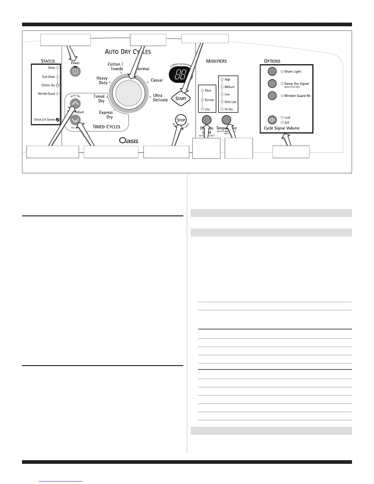
Tu rns off all indicators and
exits diagnostic mode.
Start button turns on dryer.
“ Time” turns the
t digit of the display on or off.
Less button
righ
“More Time” button turns the
left digit of the display on or off.
Power button controls Status
indicators at left.
Each button controls
its own indicators.
Rotating knob turns
indicators on or off.
Dryness Level
button controls
all indicators
above button.
Te mperature
button controls
all indicators
above button.
Figure 1.
Console Diagnostics.
➔
If none of the Console IDs above are displayed, replace the
user interface assembly. See Accessing & Removing the
Electronic Assemblies, page 11.
➔
If the motor does not turn on, go to TEST #3a, page 7.
➔ If no heat is detected, go to TEST #4, page 8.
DIAGNOSTIC: Displaying Inlet Air Flow
Used to display the airflow value at the inlet of the heater box being
measured by the machine control.
After all saved fault codes have been displayed, press the Wrinkle
Guard button to activate airflow detection. A 30 or 50 second
countdown timer will start and the dryer will turn on.
➔ If the dryer is cold, the countdown will start at 50 seconds.
NOTE: If the dryer is extremely cold (less than 40°F [4.4°C]) the
airflow may not be detected properly, and “--” will be displayed.
➔
If the dryer is hot, the countdown timer will start at 30 seconds
(cool down period) followed by an additional 50 second
countdown.
A Dryness Level modifier LED will also be illuminated to indicate the
airflow range corresponding to the number displayed.
■
The More LED will be illuminated for airflow readings above 40 cfm.
■
The Normal LED will be illuminated for airflow readings between
29 and 40 cfm.
■
The Less LED will be illuminated for airflow readings less than
29 cfm.
➔
If airflow value is low, check to make sure the lint screen is
clean, the door seal is in place and the vent is not obstructed.
DIAGNOSTIC: Displaying Line Voltage
Used to display the line voltage currently being measured by the
machine control:
After all saved fault codes have been displayed, press the Cycle
Signal button. The last 2 digits of the voltage value will be displayed
on the dual 7-segment display.
A Dryness Level modifier LED will also be illuminated to indicate the
voltage range corresponding to the number displayed. The Dryness
Level LEDs relate to specific voltage ranges as follows:
■
The More LED will be illuminated for high voltage readings (above
260 VAC).
■
The Normal LED will be illuminated for normal voltage readings
(200-260 VAC).
■
The Less LED will be illuminated for low voltage readings (below
200 VAC).
➔
If the line voltage is not seen on L2 the display will flash
L2.
Go to TEST #1, page 6.
DEACTIVATING THE DIAGNOSTIC TEST MODE
Press the Stop button twice to exit diagnostics.
ACTIVATING THE MANUAL LOAD TEST
1. Be sure the dryer is in standby mode (plugged in with all
indicators off, or with only the Clothes Dry indicator on).
2. Select any one button (except Stop) and follow the steps below,
using the same button (remember the button):
Press/
hold 2-5
seconds
➔
Release
for 2-5
seconds
➔
Press/
hold 2-5
seconds
➔
Release
for 2-5
seconds
➔
Press/
hold 2-5
seconds
➔
Release
for 2-5
seconds
➔
Press/
hold 2-5
seconds
88 flashes momentarily, the motor starts right away, and the Heavy
Duty LED flashes (this step starts the Manual Load sequence):
1. Turn on motor.
➔
Flash “Heavy Duty” LED.
Now press any key (except Stop) and the control will advance
through each step of the following sequence:
SINGLE ELEMENT MODELS:
2. Motor + heater.
➔
Flash “Casual” LED.
3. No loads on (motor + heater off).
➔
Flash “Normal” LED.
4. Repeat using same button.
➔
Start sequence again at 1.
DUAL ELEMENT MODELS:
2. Motor + heater 1.
➔
Flash “Casual” LED.
3. Motor + heater 2.
➔
Flash “Timed Dry” LED.
4. Motor + heater 1 + heater 2 + drum light.
➔
Flash “Drum Light” LED.
5. No loads on (motor + heaters off).
➔
Flash “Normal” LED.
6. Repeat using same button.
➔
Start sequence again at 1.
DEACTIVATING THE MANUAL LOAD TEST
Press the Stop button to exit this mode.