TECH SHEET - DO NOT DISCARD PAGE 3
FOR SERVICE TECHNICIAN’S USE ONLY PART NO. W10035270
DISPLAY DESCRIPTION EXPLANATION / RECOMMENDED PROCEDURE
PF
Power
Failure
PF flashes to indicate that a power failure
occurred while the dryer was running. Press
START to continue the cycle, or press STOP to
clear the display.
AF
Restricted
Airflow
Condition
AF flashes if a restricted airflow condition exists.
Check to make sure the lint screen is clean, the
door seal is in place and the vent is not
obstructed.
F-01
Primary
Control
Failure
F-01 flashes when there is a primary control
failure. Replace the machine control electronics.
See Accessing & Removing the Electronic
Assemblies, page 11.
F-02
Keypad/
User Interface
Failure
F-02 flashes when there is a stuck button or user
interface mismatch. This fault code will ONLY
appear when in the diagnostic test mode. See
TEST #6, page 10.
F-22
Exhaust
Thermistor
Open
F-22 flashes if the exhaust thermistor is open.
See TEST #4a, page 9.
F-23
Exhaust
Thermistor
Shorted
F-23 flashes if the exhaust thermistor has
shorted. See TEST #4a, page 9.
F-24
Inlet
Thermistor
Open
F-24 flashes if the inlet thermistor is open.
This fault code will ONLY appear when in the
diagnostic test mode. See TEST #4a, page 9.
F-25
Inlet
Thermistor
Shorted
F-25 flashes if the inlet thermistor is shorted.
This fault code will ONLY appear when in the
diagnostic test mode. See TEST #4a, page 9.
F-26
Motor Drive
System Failure
F-26 flashes if there is a motor drive system
failure. See TEST #3a, page 7.
F-28
Moisture
Sensor Open
F-28 flashes if the moisture sensor strip is open.
This fault code will ONLY appear when in the
diagnostic test mode. See TEST #5, page 10.
F-29
Moisture
Sensor
Shorted
F-29 flashes if the moisture sensor strip has
shorted. This fault code will ONLY appear when in
the diagnostic test mode. See TEST #5, page 10.
F-30
Restricted
Airflow
Condition
F-30 flashes if a restricted airflow condition
exists. This fault code will ONLY appear when in
the diagnostic test mode. Check to make sure the
lint screen is clean, the door seal is in place and
the vent is not obstructed.
f-40
Communication
Error
F-40 flashes if the communication between the
machine control and motor control is lost. See
TEST #3b, page 8.
f-41
Blower Motor
Failure
F-41 flashes when there is a blower motor failure.
See TEST #3b, page 8.
f-42
Undervoltage
Failure
F-42 flashes if the motor control detects a voltage
less than 90 VAC. See TEST #1, page 6 and
DIAGNOSTIC: Displaying Line Voltage, page 2.
f-43
Undervoltage
Warning
F-43 flashes if the motor control detects a low
voltage condition. The dryer will continue to run at
a set blower speed. See TEST #1, page 6 and
DIAGNOSTIC: Displaying Line Voltage, page 2.
f-44
Motor Control
Failure
F-44 flashes when there is a motor control
electronics failure. See TEST #3b, page 8.
f-45
Motor Control
Speed Sensor
Error
F-45 flashes when there is a motor control
electronics speed sensor failure. See TEST #3b,
page 8.
f-46
Blower Motor
Error
F-46 flashes if the motor control detects an
over-current or an over-torque condition. See
TEST #3b, page 8.
DISPLAY FAULT CODES
The fault codes below would be indicated when attempting to start a
drying cycle or after activating the diagnostic test mode.
PROBLEM POSSIBLE CAUSE / TEST
NOTE: Possible Cause/Tests MUST be performed
in the sequence shown for each problem.
WON’T POWER UP.
(No response when
buttons are pressed.)
1. Supply connections. See TEST #1, page 6.
2. Check harness connections.
3. User interface assembly. See TEST #6, page 10.
WON’T START CYCLE
WHEN START BUTTON
IS PRESSED.
1. If number display flashes, check to be sure the
door is completely shut, and press and hold down
START for about 1 second.
2. See TEST #3a, page 7.
3. See TEST #7, page 10.
WON’T SHUT OFF
WHEN EXPECTED.
1. Check STOP button. See TEST #6, page 10.
2. User interface assembly. See TEST #6, page 10.
3. Moisture sensor. See TEST #5, page 10.
CONTROL WON’T
ACCEPT SELECTIONS.
User interface assembly. See TEST #6, page 10.
WON’T HEAT.
1. Heater. See TEST #4, page 8.
2. Check harness connections.
3. Check installation.
HEATS IN AIR CYCLE.
Heater. See TEST #4, page 8.
SHUTS OFF BEFORE
CLOTHES ARE DRY.
1. Check the dryness setting for auto cycles.
2. Check for full lint screen.
3. Check for clogged vent.
4. Moisture sensor. See TEST #5, page 10.
5. Dryness level adjust. See Adjusting
Customer-Focused Drying Modes, page 11.
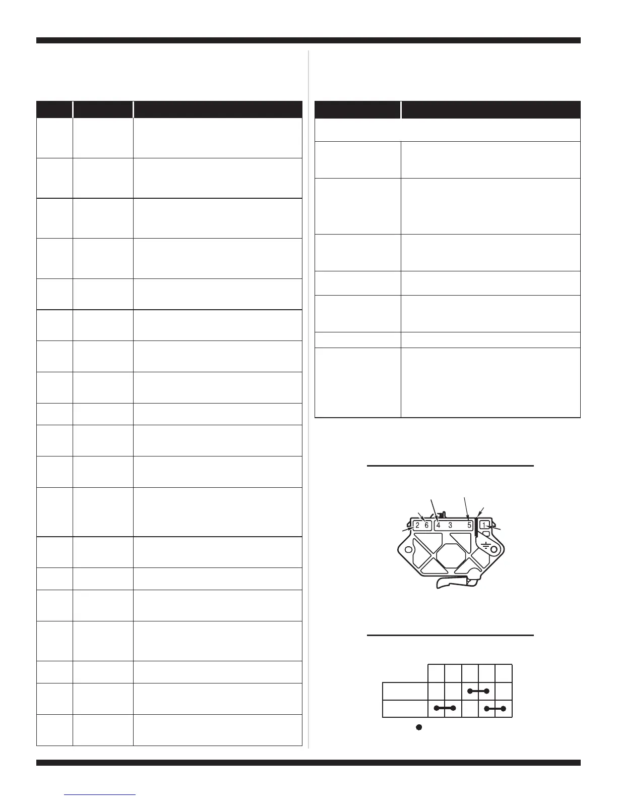
TROUBLESHOOTING GUIDE
Some tests will require accessing components. See figure 2, page 6 for
component locations.
Red
Blue
Blue-White
Green-Yellow
Red
Black-White
PLUGGABLE DRIVE MOTOR SWITCH
1M 2M 3M 5M 6M
=
Contacts closed
Contacts
Function
Start
Run
CENTRIFUGAL SWITCH (MOTOR)