15
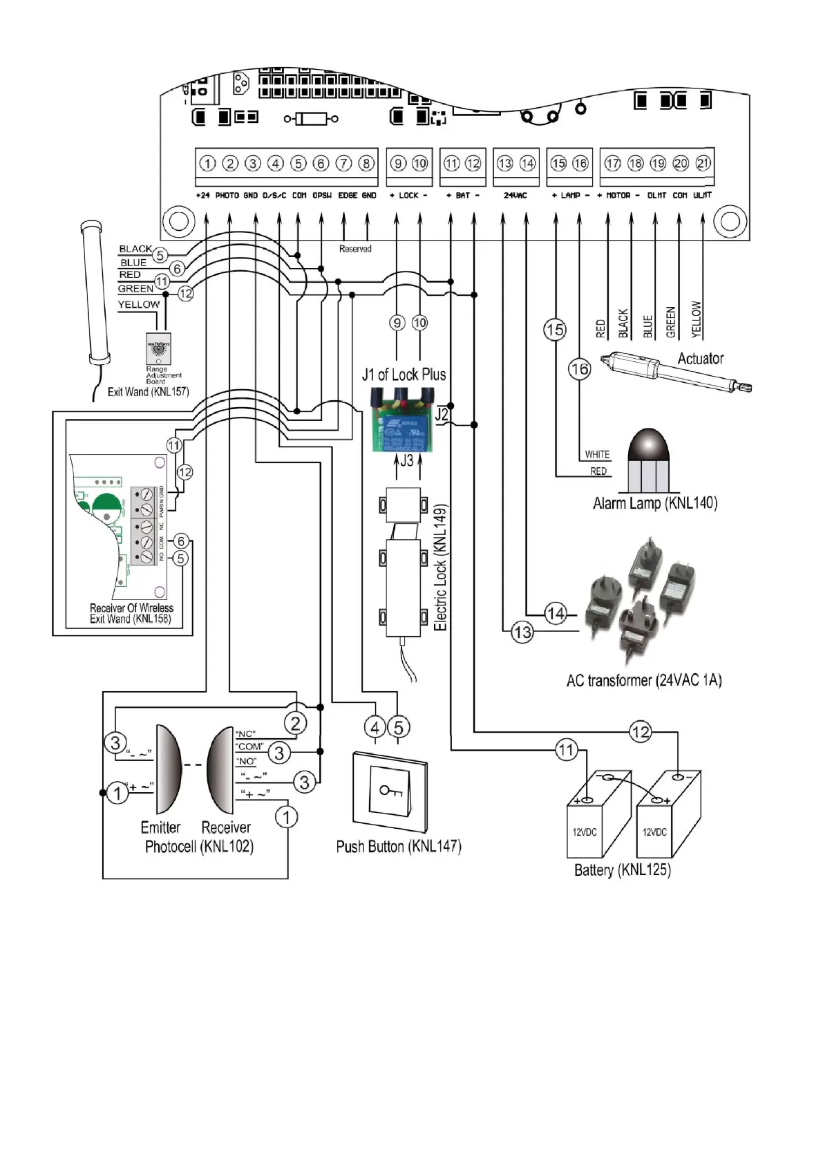
1. Actuator
Insert the stripped cable wires into the appropriate terminals on the opener terminals block. The red wire should
be inserted into the “ +MOTOR” terminal(#17), the black wire into “ MOTOR-” terminal (#18), the blue wire into
“ DLMT” terminal(#19), the green wire into “ COM” terminal(#20), and the yellow wire into “ ULMT” terminal
(#21).
2. Battery (Required but not included)
The “ 24V+” of the battery should be wired to the +BAT (#11) terminal, “ 24V-” should be wired to “ BAT-” (#12)
terminal. 2*12VDC batteries can be connected in series to become 24V.
3. AC transformer (Only used to charge the batteries)
Insert the stripped cable wires into AC24V (#13) terminals to the control board. No matter the polarity.