Do you have a question about the Kenner KND800 and is the answer not in the manual?
Ensure gate track is linear, horizontal, and wheels suitable for free movement.
Verify gate structure strength, rigidity, plumbness, and levelness.
Confirm fence posts are concrete-mounted and gate stops are in position.
Mount the opener securely in a level, parallel position after checking gate movement.
Connect the gate opener to the power outlet using appropriate wiring and RCD protection.
Wiring for backup power using batteries or solar systems for continuous operation.
Wire batteries and solar controller for AC backup power, with solar charging capabilities.
Wire batteries and solar panel as the main power source for gate operation without AC.
Connect the motor wires (YELLOW/RED) to terminals 1 and 2 on the control board.
Wire limit switches (YELLOW/BLACK/RED) to terminals 3, 4, and 5 of the control board.
Connect the alarm lamp wires (WHITE/RED) to terminals 6 and 7 of the control board.
Connect photocell emitter and receiver wires to specified terminals on the control board.
Connect push button to terminals 16/17 and exit wand wires to terminals 14, 15, 18, 19.
Connect battery to terminals 10/11 and external receiver wires to terminals 16, 17, 18.
Connect wired keypad wires (RED/BLACK/BLUE/PURPLE) to terminals 18, 17, 16, 17.
Configure DIP switches for pedestrian mode, soft stop, auto-close time, and direction.
Detailed explanation of DIP switch settings for pedestrian mode, soft stop, and auto-close.
Adjust Potentiometers A and B for closing and opening stall force respectively.
Test gate reversing function by ensuring it stops/reverses upon hitting an object.
Pairing up to 10 remotes directly or 200 via external receiver.
How to use remote buttons A, B, C, and D for various gate opener functions and modes.
Check power cord, transformer voltage, control board fuse, and battery charge status.
Resolve remote issues, gate stopping/reversing, or gate opening but not returning.
Address closing failures and perform regular maintenance checks for proper operation.
This document is a user manual for the KENNER Sliding Gate Opener, available in two models: KND800 and KND1600. It provides comprehensive instructions for installation, operation, troubleshooting, and maintenance, emphasizing safety precautions throughout.
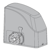
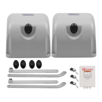
The KENNER Sliding Gate Opener is an automation system designed to open and close sliding gates. It is suitable for residential use and can be powered by AC electricity, or by batteries, with optional solar panel charging for off-grid or backup power. The system incorporates various safety features and can be integrated with a range of accessories for enhanced functionality and control.
| Specification | KND800 | KND1600 |
|---|---|---|
| Power input | 220~240V/50Hz | 220~240V/50Hz |
| Motor voltage | 24VDC | 24VDC |
| Rated power | 180W | 450W |
| Gate moving speed | 21 cm/s (8.3 in/s) | 21 cm/s (8.3 in/s) |
| Max torque | 15Nm | 30Nm |
| Environmental conditions | -22°C ~ +55°C (-4°F to 122°F) | -22°C ~ +55°C (-4°F to 122°F) |
| Protection class | IP44 | IP44 |
Regular maintenance is crucial for the safe and proper operation of the gate opener. The manual recommends checking the following items every six months:
The manual also provides detailed troubleshooting steps for common issues such as the opener not running (Power LED OFF or ON), remote control not working, the gate starting but immediately stopping or reversing, and the gate opening but failing to close. These steps often involve checking power connections, fuses, limit switches, motor wiring, battery voltage, solar controller status, photocell alignment, clutch adjustment, stall force settings, and magnet positions.
| Brand | Kenner |
|---|---|
| Model | KND800 |
| Category | Gate Opener |
| Language | English |