Connecting the control board
1. Motor
The YELLOW wire of the motor should be connected to the “1” terminal.
The RED wire of the motor should be connected to the “2” terminal.
2. Limit Switches
The YELLOW wire of the limit switches should be connected to the “3” terminal.
The BLACK wire of the limit switches should be connected to the “4” terminal.
The RED wire of the limit switches should be connected to the “5” terminal.
3. Alarm Lamp (24VDC)
The WHITE wire of the alarm lamp should be connected to the “6” terminal.
The RED wire of the alarm lamp should be connected to the “7” terminal.
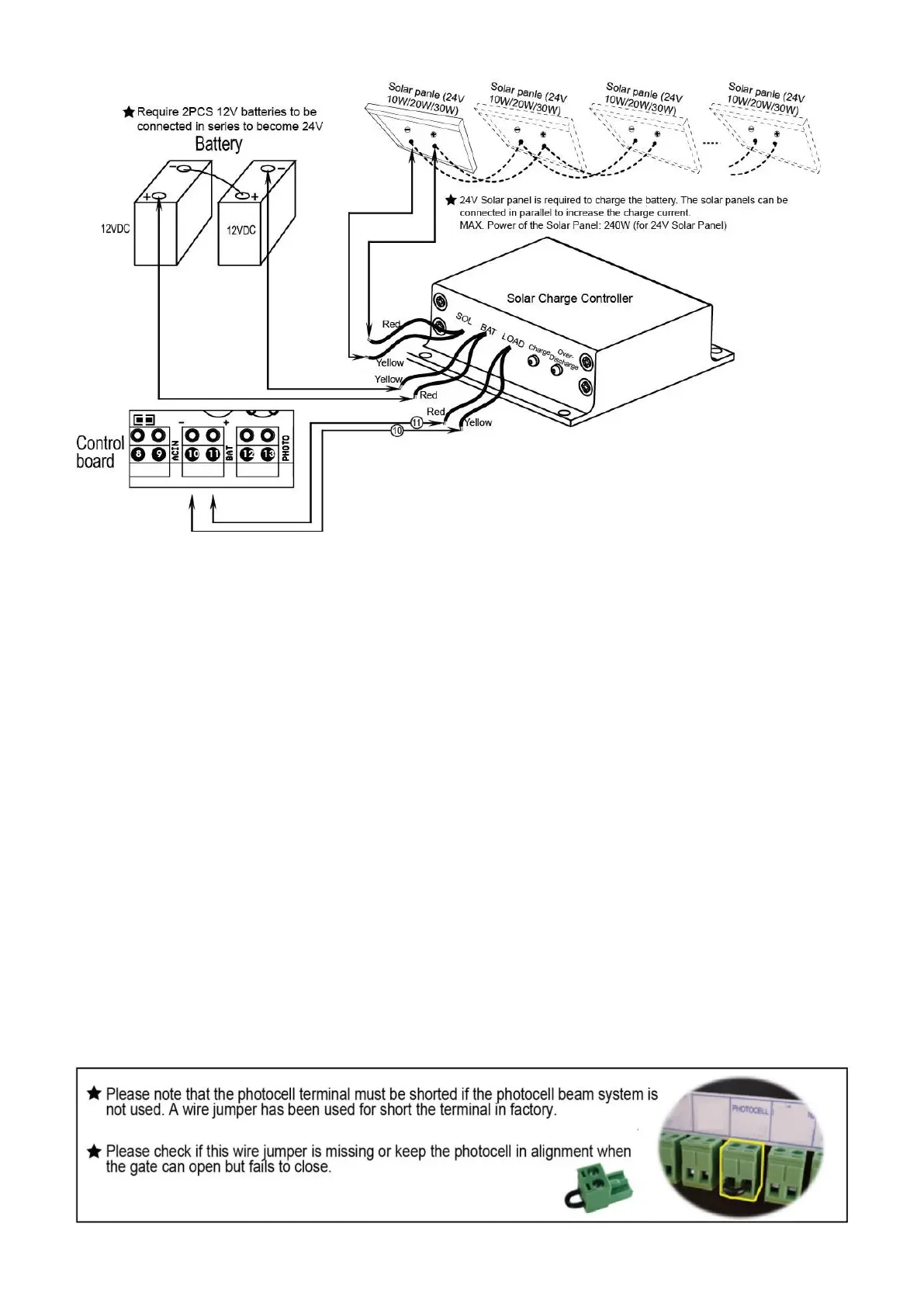
4. Photocell
Use a 2-core cable to connect the “- ~” terminal of the photocell’s emitter to the “19” terminal, the “+ ~”
terminal to the “18” terminal. Also the “- ~” and “+ ~” terminals of the photocell’s receiver should be
connected to the “19” and “18” terminals in parallel.
Use another 2-core cable to connect the “NC” terminal of the receiver to the “13” terminal, the “COM”