16
4. Alarm Lamp (optional)
The red wire of the alarm lamp should be inserted into either LAMP (#15) terminal, the white wire into the other
one (#16).
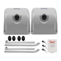
5-1. Photocell Beam System (PBS) (optional)
Use a 2-core cable to connect the “ + ~” terminal of the photocell emitter to the “+24” (#1) terminal, the “ - ~”
terminal to the “GND” (#3) terminal. Also the “ + ~” and “ - ~” terminals of the photocell receiver should be
connected to the “+24” and “GND” terminals in parallel.
Use another 2-core cable to connect the “ NC” terminal of the receiver to the “PHOTO”(#2) terminal, the “ COM”
terminal to the“GND”(#3) terminal.
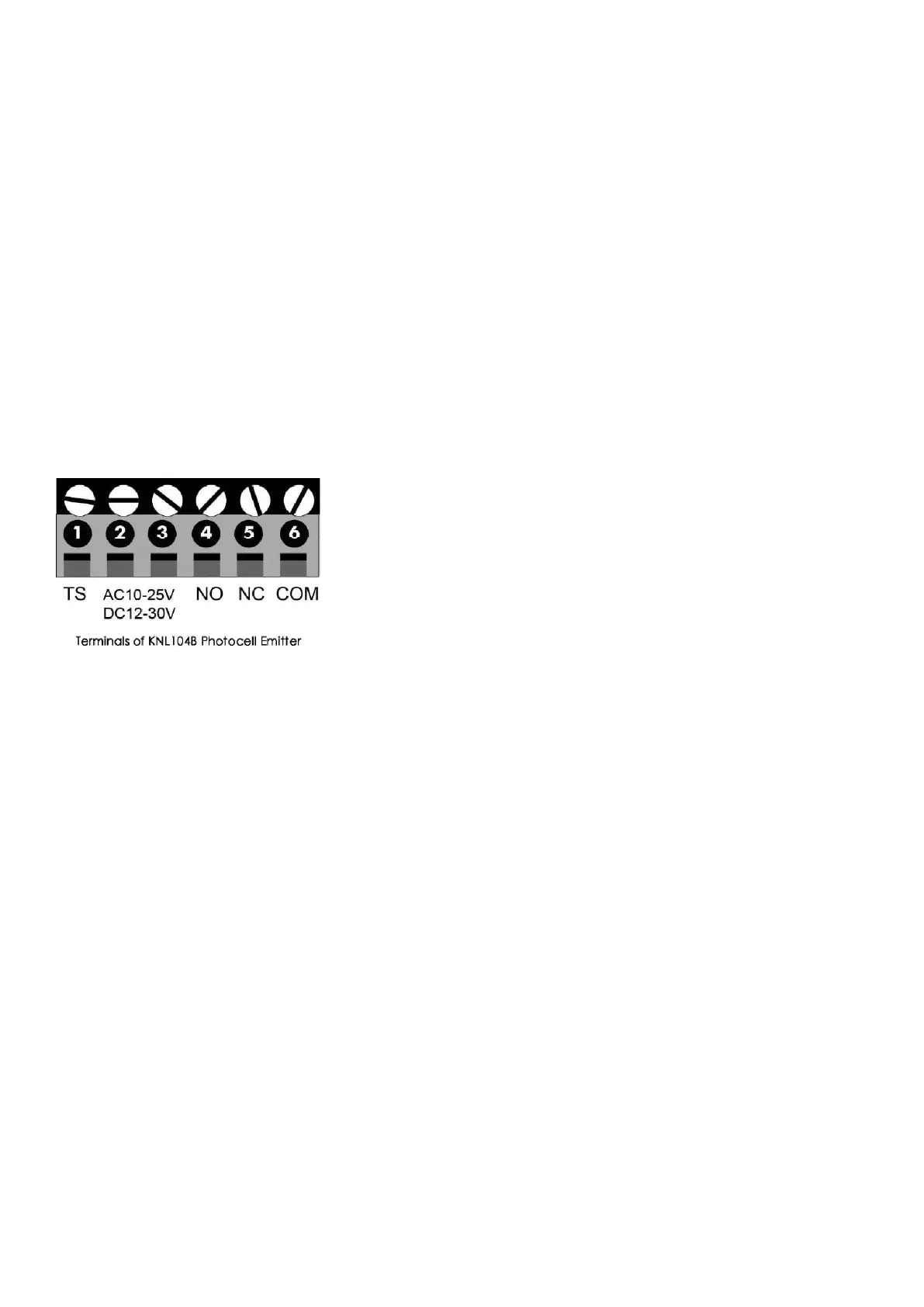
5-2. KNL104B Reflective Photocell (optional)
Use a 2-core cable to connect the “ #2” terminal of the KNL104B photocell to the “ +24” (#1) terminal of gate
opener control board, the “ #3" terminal of the KNL104B photocell to the “ GND” (#3) terminal of gate opener
control board.
Use another 2-core cable to connect the “ NC” (#5) terminal of the KNL104B photocell to the “ PHOTO” (#2)
terminal of the gate opener control board, the “ COM” (#6) terminal of KNL104B photocell to the “ GND” (#3)
terminal of gate opener control board.
6. Push Button (optional)
The push button should be wired to the “#4 and “#5” terminals. No matter the polarity. The gate operator works
alternately by pressing the button (open-stop-close-stop-open).
7. Electric Lock (optional)
A lock plus board (should be purchased separately) is required to connect the electric lock to the control board.
The 2 wires of J1 of lock plus should be wired to the “9#” and “10#” terminal of the control board. No matter the
polarity. Red wire of J2 should be wired to the 11# terminal and yellow wire of J2 should be wired to the 12#
terminal. Red wire of J3 should be connected to the red wire of electric lock and also the yellow wire of J3
should be connected to the yellow wire of electric lock.
8. Exit Wand (optional)
The BLACK wire of the exit wand should be connected into the “#5” terminal.
The BLUE wire of the exit wand should be connected into the “#6” terminal.
The RED wire of the exit wand should be connected into the “#11” terminal.
The GREEN wire of the exit wand should be connected into the “#12” terminal.
The sensitivity adjustment board should be wired to the GREEN wire and the YELLOW wire of the wand. No
matter the polarity.
9. Wireless Exit Wand (optional)
The “ NO” terminal of the receiver should be wired to the “#5” terminal of the control board.
The “ COM” terminal of the receiver should be wired to the “#6” terminal of the control board.
The “ PWR” terminal of the receiver should be wired to the “#11” terminal of the control board.
The “ GND” terminal of the receiver should be wired to the “#12” terminal of the control board.