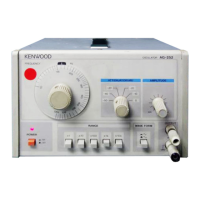
Front panel
® Index mark
Indicates dial divisions.
©
Scale
plate
Calibrated
with
10—100 divisions.
@
Frequency dial
Adjusts oscillation , frequency.
Frequency
can be read directly by
multiplying
the
indication
on the scale plate by the magnification
of the
FREQ.
RANGE
switch.
©
POWER
The
power switch. When depressed, the power is
applied to the AG-252. Pressing the switch again
makes
it released and turns the power off.
© Pilot lamp
Indicates
that
the power is applied.
©
FREQ.
RANGE
(Hz)
These
switches provide five selections of oscillation
frequency range :
x
1
:
10Hz~100Hz
xlO : 100Hz~lkHz
xlOO : 1kHz~l0kHz
x
1k : 10kHz-100kHz
xlOk : 100kHz-1MHz
® WAVE FORM
Selects
a waveform of
output
signal. When
depressed,
it selects sine wave( — ).
When released, it selects square wave( Ij ).
©
OUTPUT
Delivers
output
signal in sine or square waveform
whichever is selected. The one labeled £ is the
GND
(case
GND) terminal.
©
ATTENUATOR
(dB)
Attenuates the
output
to one of six levels :
0 to -50dB in steps of 10dB.
© AMPLITUDE
A
controller
continuously changing the
amplitude
of
output
voltage.
6


 To Next Page