2)
Turn the
FREQ.
DIAL © to align "15" on
the
scale
plate to the index mark ®.
Now 1.5kHz has been selected.
15
x 100 = 1500Hz = 1.5kHz
4.
Adjusting the
output
voltage
The
voltage
output
to the
OUTPUT
terminal @,
whether sine or square wave, can be continuously
varied
with
the
AMPLITUDE
© and stepped down
with
the
ATTENUATOR
®.
Example
: Adjusting
output
voltage to lOmVrms
1)
Connect a voltmeter capable of measuring
1Vrms
of AC voltage to the
OUTPUT
terminal ®.
2)
Set the
ATTENUATOR
© OdB and adjust
the
AMPLITUDE
© so that the voltmeter
may
indicate 1Vrms. Now a IVrms voltage
is
output
to the
OUTPUT
®.
3)
Set the
ATTENUATOR
© to -40dB. The
voltmeter indicates nearly 0V, but in fact
the voltage of 10mVrms is correctly
output
to the
OUTPUT
®.
5.
How to use the
sync
input
terminal
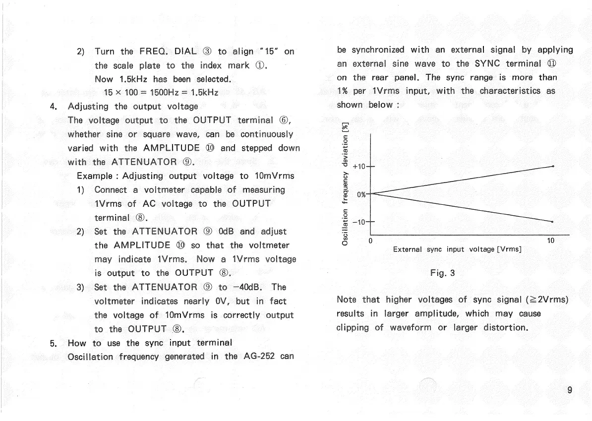
Oscillation frequency generated in the AG-252 can
be synchronized
with
an external signal by applying
an
external sine wave to the
SYNC
terminal ©
on the rear panel. The
sync
range is more than
1%
per 1Vrms
input,
with
the characteristics as
shown below :
External
sync
input
voltage [Vrms]
Note that higher voltages of
sync
signal (^2Vrms)
results
in larger amplitude, which may
cause
clipping of waveform or larger distortion.
9
Oscillation
frequency
deviation
[%]
Fig.
3


 To Next Page