Do you have a question about the Kenwood C-V150 and is the answer not in the manual?
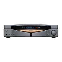
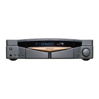
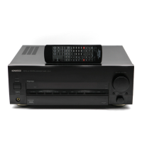
Describes the purpose of various buttons and indicators on the main unit.
Explains the system's standby mode and its display.
Details the controls and screen elements of the Graphical Remote Control.
Provides notes on operating range and potential issues.
Details new features like amp, tuner, and voice activation.
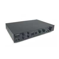
Describes power, volume, and default operational data.
Details microprocessor connections and key matrix.
Details the function of each pin on the microprocessor.
Lists tuner settings based on destination.
Differentiates models based on diode settings.
Describes FM discriminator and distortion adjustments.
Lists possible error messages and their descriptions.
Lists components for the C-V100 model.
Lists components for other models.
Details technical specs for C-V350 and C-V150.
Details technical specs for C-V300 and C-V100.
| Damping Factor | 60 |
|---|---|
| Type | Stereo Amplifier |
| Frequency Response | 5Hz to 100kHz |
| Total Harmonic Distortion (THD) | 0.7% |
| Input Sensitivity | 150mV (line) |
| Output | Speaker Outputs, Headphone Jack |