Do you have a question about the Kenwood TL-922A and is the answer not in the manual?
Describes amplifier class and tube type for optimal performance.
Highlights stable, high RF output for continuous use and advanced engineering.
Mentions minimized IMD via negative RF feedback for cleaner signals.
Notes no warm-up needed due to fast-heating tubes, improving usability.
Explains the double safety system for high voltage protection and user safety.
Describes circuit to reduce power tube deterioration and extend tube life.
Explains SSB/CW mode selection for optimal PEP output and heat management.
Allows setting the amplifier in a straight-through state for flexibility.
Adjusts ALC threshold to prevent overdriving tubes and ensure linearity.
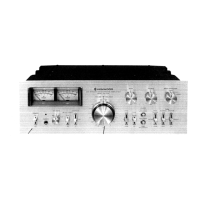
Describes meters for monitoring plate current, grid current, RF output, or HV.
Highlights die-cast panels and recessed handles for durability and portability.
Features a reduction gear for easy tuning and preventing miss-tuning.
Mentions sophisticated design to aesthetically match Trio-Kenwood equipment.
Lists supplied accessories with quantities for initial setup.
Details procedures for installing the two Eimac 3-500Z power tubes safely.
Provides advice on placement, ventilation, and stability for optimal operation.
Advises on using a power line with sufficient current capacity for performance.
Explains how to change input voltage from 120V to 240V as required.
Instructs on connecting the power cable plug to the wall outlet.
Details suitable exciters and output power requirements for driving the amplifier.
Specifies requirements for the antenna impedance and power rating for optimal performance.
Emphasizes connecting GND posts for shock and RFI prevention.
Guides on interconnecting with supplied cables for proper operation.
Details functions of front panel controls like IP Meter, ON AIR Indicator, and BAND Selector.
Describes rear panel connectors and controls like Cooling Fan, RF Input, and GND Post.
Lists essential checks before powering on the amplifier for safe operation.
Provides step-by-step instructions for CW mode tuning and operation.
Guides on tune-up procedures for SSB mode to ensure linearity and performance.
Refers to CW tune-up procedures for RTTY operation, noting key-down limits.
Explains how to adjust ALC control to prevent overdrive and distortion.
Details how to calibrate the RF output meter reading for accuracy.
Describes the thermal protection circuit for the HV transformer and its behavior.
Provides guidance on safe handling and transport of the unit, including weight.
Describes the amplifier circuit, input matching, and tube operation principles.
Explains the voltage doubling rectifier, transformers, and capacitor bank.
Details the circuit that keeps the fan running after power-off for tube cooling.
Explains how plate current, grid current, RF output, and HV are measured.
Describes the discharge gap device for preventing high voltage spikes at antenna relay terminals.
Advises on regular vacuuming of internal components to prevent arcing and overheating.
Guides on locating and replacing blown fuses with correct ratings.
Refers to Section 2.2 for detailed power tube replacement procedures.
States the circuit is factory preset and requires professional adjustment for RF/DC voltages.
Lists common causes and remedies for the unit not producing any output power.
Identifies reasons for low output and their solutions, including IP and HV readings.
Explains causes for incorrect RF meter readings and how to adjust them.
Addresses issues causing fuses to blow, such as incorrect installation or line voltage problems.
Discusses causes for overheating and how to secure covers properly.