Do you have a question about the Kenwood TL-120 and is the answer not in the manual?
Monitors output wave level and controls output power.
Protects against mis-matched loads and voltage drops by reducing amplifier power.
Fan control by temperature and protection against incorrect band settings.
Terminals for measuring collector current and overheat protection circuits.
Technical specs and maximum ratings for the SRF 1714 power amplifier transistor.
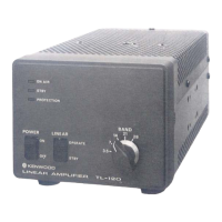
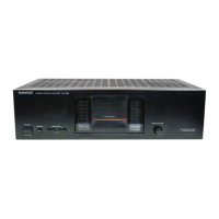
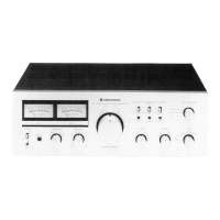
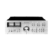
Identification of controls and indicators on the front panel.
Identification of input/output connectors on the rear panel.
Identification of major internal assemblies visible from the top.
Schematic and component layout for the Power Amplifier unit.
Schematic and component layout for the Filter unit.
Schematic and component layout for the LED PC Board.
Schematic and component layout for the Control unit.
Information on resistor types, wattage, value, tolerance, and capacitor types/values.
Explanation of how capacitor values are coded and examples.
List of general parts and detailed breakdown for the PA Unit.
Detailed list of parts for the Filter and Control Units.
List of items included in the product packaging.
Diagram illustrating the removal of the unit's outer casing.
Exploded view showing front panel and PC board mounting disassembly.
Exploded views for rear panel and PA unit component disassembly.
Steps to diagnose and resolve problems with power supply, voltage, and ALC settings.
Steps for troubleshooting inoperative fans and protection circuit activation.
Required equipment, connection steps, and initial settings for adjustments.
Procedures for adjusting the 9V DC-DC converter and base current.
Alignment steps for the Control, Filter, and PA Unit PC boards.
Procedures for adjusting the ALC circuit and protection functions.
Graph showing output power as a function of input signal level.
Graph showing output power and efficiency across carrier frequencies.
Complete schematic diagrams for the PA, Filter, and Control units.
Graphs illustrating spurious response (harmonics) at various frequencies and powers.