Do you have a question about the Kenwood 500 and is the answer not in the manual?
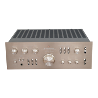
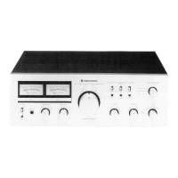
Identifies front panel controls, inputs, and indicators.
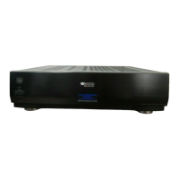
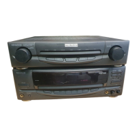
Identifies rear panel connections and outputs.
Labels major internal circuit boards and components.
Details power output, phono impedance, and selector steps.
Steps to remove the Power Amplifier module.
Steps to remove Tone and Preamp modules.
Explains input impedance, volume control, and loudness functions.
Details the operation of the power supply circuits.
Describes the direct-coupled DC amplifier design.
Explains the circuit protecting speakers from DC voltage.
Details the four-stage equalizer amplifier.
Describes the flat amplifier and BAX tone control unit.
Explains gain boost for presence control.
Details negative feedback filters and constant current circuits.
Procedures for adjusting VRe1 and VRe3.
Procedure for adjusting VRe2 for bias current.
Diagnosing output issues for the power amp.
Diagnosing output issues for tone/filter amps.
Diagnosing output issues for the preamp.
Addresses frequency response deviations from RIAA standard.
List of capacitors used in the units.
List of resistors used in the units.
List of transistors and diodes.
Lists variable resistors and switches.
Lists other parts like hardware, fixtures.
Lists parts for Power Supply unit B.
Lists parts for Power Supply unit A.
Lists parts for the Power Amplifier unit.
Lists parts for the Preamplifier unit.
Lists parts for the Tone Amplifier unit.
Lists parts for the Filter unit.
Lists parts for the Impedance Selector unit.
Layout for Power Supply unit A.
Layout for the Impedance Selector.
Layout for Power Supply unit B.
Layout for the Power Amplifier unit.
Layout for the Preamplifier unit.
Layouts for Tone and Filter Amplifier units.
Lists alternative semiconductor parts.
Details power output, distortion, frequency response.
Covers preamp sensitivity, S/N, tone controls, loudness, power requirements, dimensions, and weight.