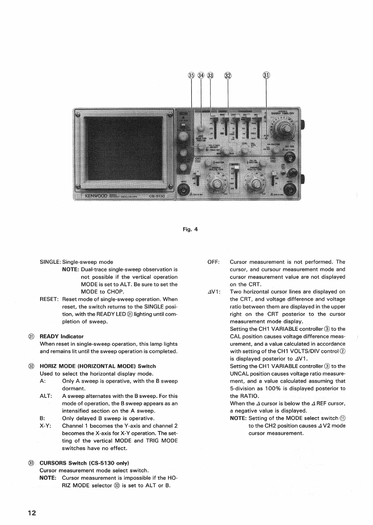
Fig.
4
SINGLE:
Single-sweep mode
NOTE:
Dual-trace singie-sweep observation is
not possible if the vertical operation
MODE
is set to ALT. Be sure to set the
MODE
to
CHOP.
RESET:
Reset
mode of single-sweep operation. When
reset,
the switch returns to the
SINGLE
posi-
tion,
with
the
READY
LED
@
lighting until
com-
pletion
of sweep.
©
READY
Indicator
When reset in single-sweep operation, this lamp lights
and remains lit
until
the sweep operation is completed.
© HORIZ MODE (HORIZONTAL MODE) Switch
Used
to select the horizontal display mode.
A:
Only A sweep is operative,
with
the B sweep
dormant.
ALT:
A sweep alternates
with
the B sweep. For this
mode of operation, the B sweep appears as an
intensified section on the A sweep.
B:
Only delayed B sweep is operative.
X-Y:
Channel 1 becomes the
Y-axis
and channel 2
becomes the
X-axis
for X-Y operation. The set-
ting
of the vertical MODE and
TRIG
MODE
switches
have no effect.
(§)
CURSORS
Switch (CS-5130 only)
Cursor
measurement mode select switch.
NOTE:
Cursor measurement is impossible if the HO-
RIZ
MODE selector
(32)
is set to ALT or B.
OFF:
Cursor measurement is not performed. The
cursor, and cursour measurement mode and
cursor measurement value are not displayed
on the CRT.
A^/^:
Two horizontal cursor lines are displayed on
the CRT, and voltage difference and voltage
ratio
between them are displayed in the upper
right
on the CRT posterior to the cursor
measurement mode display.
Setting the
CH1
VARIABLE
controller ® to the
CAL
position
causes
voltage difference
meas-
urement, and a value calculated in accordance
with
setting of the
CH
1
VOLTS/DIV
control
@
is
displayed posterior to AV\.
Setting the
CH
1
VARIABLE
controller © to the
UNCAL
position
causes
voltage
ratio
measure-
ment, and a value calculated assuming
that
5-division as 100% is displayed posterior to
the
RATIO.
When the A cursor is below the A
REF
cursor,
a
negative value is displayed.
NOTE:
Setting of the MODE select switch
(Q)
to the CH2
position
causes
A V2 mode
cursor measurement.
12

 Loading...


