Do you have a question about the Kenwood DM-3090 and is the answer not in the manual?
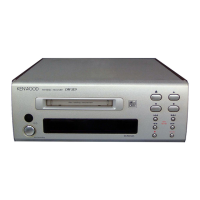
Identifies and explains the functions of the front panel controls and indicators.
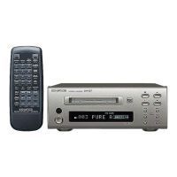
Details the buttons and functions of the remote control unit for operating the device.
Provides step-by-step instructions for removing main parts of the MD mechanism.
Describes the pin functions and operations of the RF signal control IC.
Details the pin functions and operations of the ENDEC/ATRAC processor IC.
Explains the pin functions and operations of the MD system microcomputer.
Details the pin functions and operations of the system control microcomputer.
Lists error messages, their meanings, and corrective actions for common issues.
Details specific mechanism errors and their corresponding troubleshooting steps.
Provides diagnostic flowcharts for various operational failures like power or playback issues.
Outlines prerequisites and test discs required for calibration procedures.
Explains how to enter and navigate the device's test and adjustment modes.
Covers AUTO pre-adjustment and AUTO adjustment modes for device calibration.
Details the RESULT sub-mode and final adjustment mode for detailed calibration.
Explains manual adjustment procedures for low reflection and high reflection discs.
Describes TEST-PLAY and TEST-REC modes for specific functional testing.
Covers optical pickup grating and jitter adjustments for mechanism calibration.
Illustrates the mechanical components and their assembly for the MD mechanism.
Shows the overall assembly of the device unit, including front panel and main chassis parts.
| frequency response (playback mode) | 8 Hz ~ 20 kHz, ± 1 dB |
|---|---|
| signal to noise ratio (playback mode) | More than 100 dB |
| wow & flutter | Less than unmeasurable limit |
| analog input sensitivity / input impedance | 0.5V / 22 kΩ or more |
|---|---|
| analog output level/output impedance | 2.0 V / Less than 2 kΩ |
| headphone output | 15 mW/32 Ω load |
| digital input coaxial | 0.5 Vp-p / 75 Ω |
|---|---|
| digital input optical | - 15 dBm ~ - 21 dBm |
| digital output optical | - 15 dBm ~ - 21 dBm |
| power consumption | 17 W |
|---|---|
| dimensions width | 440 mm (17 - 5 / 16”) |
| dimensions height | 94 mm (3 - 11 / 16”) |
| dimensions depth | 300 mm (11 - 13 / 16”) |
| weight | 3.55 kg (7.9 lb) |
|---|