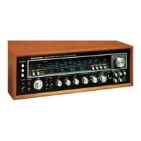
Do you have a question about the Kenwood Eleven III KR-1000 III and is the answer not in the manual?
| Brand | Kenwood |
|---|---|
| Model | Eleven III KR-1000 III |
| Category | Stereo Receiver |
| Language | English |
Procedure for stringing the dial cord on the variable capacitor and dial pulley.
Steps to remove transistors from the power supply unit's heat sink.
Steps to remove the panel assembly, including knobs and screws.
Procedure for disassembling the lamp assembly and replacing pilot lamps.
Steps to remove the power amp unit from the chassis.
Procedure for removing the pushbutton switch (B) unit from the chassis.
Description of Model Eleven III as a modification of Model Eleven II and its output power.
Explanation of the impedance detecting circuit and its effect on power output.
Detailed explanation of the Wheatstone bridge circuit for impedance detection.
Function of the memory circuit in storing and feeding detecting circuit input.
Operation of the control circuit based on memory circuit output and voltage variations.
Diagram showing Dolby NR circuit connections selected by switch S15.
Description of various Dolby NR modes like Dolby on/off, FM reproduction.
List of capacitor part numbers, types, and specifications.
List of switch part numbers and general miscellaneous components.
List of potentiometers and switches with their part numbers and descriptions.
List of resistors and semiconductor components with part numbers and types.
List of components for the Tuner unit (X05-1390-10).
List of components for the Power Amp unit (X07-1570-80).
List of components for the Control Amp unit (X11-1440-10).
List of miscellaneous parts and components for various units.
Component lists for Push Switch (B) and Tape Monitor units.
List of components for the Dolby unit (X14-1070-10).
Circuit diagram for Push Switch (A) unit (X13-2190-10).
Circuit diagram for Speaker Selector unit (X13-2390-80).
Circuit diagram for Tape Monitor unit (X13-2310-10).
Adjustment procedures for FM section tuning, IF, output, tracking, VCO, and distortion.
Adjustment procedures for AM section IF and tracking.
Adjustment procedures for BIAS and Power Meter.
Adjustment procedures for Dolby NR section calibration and level settings.
Specifications for the Standard Signal Generator used in adjustments.
Specifications for Volt Meter, Oscilloscope, Distortion Meter, and Frequency Counter.
Specifications for the Audio Signal Generator used in adjustments.