Do you have a question about the Kenwood KR-4070 and is the answer not in the manual?
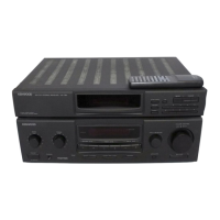
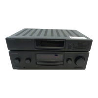
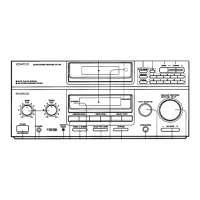
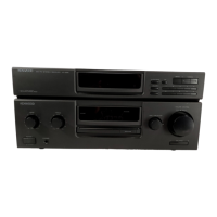
Identification of internal components and their locations within the receiver.
Step-by-step guide for properly stringing the dial cord on the receiver.
Instructions for removing the front panel assembly and associated components.
Procedures for removing audio components and power transistors.
Guide for removing the tuner block and replacing rotary wafer switches.
Method for repairing or replacing defective printed resistors on the PC board.
Explanation of FM tuner operation, muting detection, and MPX circuit.
Functionality of stereo auto switch, VCO control, and AM signal processing.
Description of EQ, tone controls, protection, and noise elimination circuits.
Parts list organized by geographical destination for service.
Lists of capacitors, resistors, and semiconductors used in the receiver.
Parts for tuner, audio sections, switches, fuses, and miscellaneous components.
Schematic diagrams for the tuner and audio units.
Guide for semiconductor substitutions and component maximum ratings.
Detailed procedures for receiver adjustments, alignment, and test equipment use.
Performance specifications for amplifier, tuner sections, and general data.
| signal to noise ratio at 65 dBf | 67 dB |
|---|---|
| power output (mono) | 72 dB |
| power output (stereo) | 40 watts per channel, minimum RMS at 8 ohms, from 20 Hz to 20, 000 Hz with no more than 0.1% total harmonic distortion |
| frequency response | 20 to 15, 000 Hz +0.5 dB, -2.0 dB |
| capture ratio | 1.0 dB |
| both channels driven | 40 + 40 watts 8 ohms at 1, 000 Hz |
| dynamic power output | 190 watts 4 ohms |
| total harmonic distortion | 0.1% at rated power into 8 ohms |
| intermodulation distortion | 0.1% at rated power into 8 ohms |
| power bandwidth | 10 Hz to 40, 000 Hz |
| damping factor | 40 at 8 ohms |
| stereo separation | 43 dB at 1, 000 Hz |
| power consumption | 300 watts at full power |
|---|---|
| dimensions | 360 mm |
| weight | 20.7 lb (9.4 kg) |
| usable sensitivity | 10.8 dBf (1.9 nV) |
|---|---|
| 50 dB quieting sensitivity (mono) | 15 dBf (3.1 µV) |
| 50 dB quieting sensitivity (stereo) | 37.2 dBf (40 µV) |
| usable sensitivity | 16 µV |
|---|---|
| signal to noise ratio | 50 dB |
| selectivity | 34 dB |