EasyManua.ls Logo

Kenwood FZDA07ELEF2 User Manual

Kenwood FZDA07ELEF2
112 pages
To Next Page IconTo Next Page
Page #1 background imageLoading...
Page #1 background image
This product uses Lead Free solder.
This product complies with the
RoHS directive for the European market.
AUDIO NAVIGATION SYSTEM
FZDA07ELEF2
FZDA07EREF2
FZDA07MRHF2
© 2007-8 CREATED IN JA PAN
B53-0559-00
(
N
)
0
SERVICE MANUAL
DISC
AUX
TON E
SURROUND
AUTO
PUSH ON/VOL
FOLDER
FRONT
FA N
BAL
SCAN
A/S
DISP
FM
AM
MODE A/C OFF
456123
MP3/WMA
KH
TUNE/TRACK
DISC
AUX
TON E
BAL
PUSH ON/VOL
FOLDER
FRONT
AUTO
OFF
DISP
SCAN
A/S
RDS
FM
AM
MODE A/C
456123
MP3/WMA
ANTI-THEFT SECURITY
RE
TUNE/TRACK
DISC
AUX
TON E
BAL
TUNE/TRACK
FOLDER
FRONT
PUSH ON/VOL
DISP
SCAN
A/S
RDS
FM
AM
MODEA/C
456123
MP3/WMA
LE
AUTO
OFF
Model Model Name Parts No.
FZDA07ELEF2 FZDA07ELEF2 86271AG100
FZDA07EREF2 FZDA07EREF2 86271AG200
FZDA07MRHF2 FZDA07MRHF2 86271AG400
SUBARU GENUINE
The knobs with numbers larger than 700 on exploded view are not supplied for service parts
because it is difficult to apply grease.
Please change to panel assy when you need repair to the knob.
The CN503 in the ELECTRIC UNIT (X34-485x-xx) is not a replaceable component.
In case of defective of this IC, replace the entire unit (X34-485x-xx).
The IC5, 9, IC21, and IC60 in the DVD unit (X37-1120-03) are not replaceable components.
When these ICs are defective, replace the whole DVD mechanism assembly (X92-5910-01).
You cannot replace only the board.
The IC3, and IC11 in the DVD unit (X37-1100-00) are not replaceable components.
When these ICs are defective, replace the whole DVD mechanism assembly (X92-5500-00).
You cannot replace only the board.
FZDA07MRHF2
FZDA07EREF2
FZDA07ELEF2
PANEL ASSY
(Y33-2872-72)
PANEL ASSY
(Y33-2872-71)
PANEL ASSY
(Y33-2870-21)
DC cord for service E30-3801-15
ANT extension cord for service E30-6255-05
Question and Answer IconNeed help?

Do you have a question about the Kenwood FZDA07ELEF2 and is the answer not in the manual?

Kenwood FZDA07ELEF2 Specifications

General IconGeneral
BrandKenwood
ModelFZDA07ELEF2
CategoryCar Navigation system
LanguageEnglish

Summary

Gear Position in DVD Mechanism

System Block Diagram

Signal Level Diagram

Components Description

Power Supply Unit Components

Lists components and their functions for the power supply unit.

Tuner Unit Components

Lists components and their functions for the tuner unit.

Synthesizer Unit Components

Lists components and their functions for the synthesizer unit.

System Microcomputer Terminal Description

Test Mode Overview

Engineering Diagnosis Overview

Details the purpose and intended users of the diagnostic mode.

Entering Diagnostic Commands

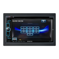
Procedure for entering diagnostic mode via touch panel sequence.

Diagnostic Mode Cancel Conditions

Describes how to exit diagnostic mode and conditions for clearing it.

Diagnostic Mode Screen and Interrupt Conditions

Details screen display behavior and handling of interrupts in diagnostic mode.

Diagnostic Mode Panel Key Enable Conditions

Specifies which panel keys are enabled or disabled in diagnostic mode.

Diagnostic Mode Display Conditions

Describes number padding and suppression rules in diagnostic mode displays.

Engineering Diagnosis Screen Tree

Engineering Diag Menu (Page1) Screen

Version Information Screen

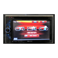
Displays model, program, ROM, map, and data file versions.

GPS Information Screen

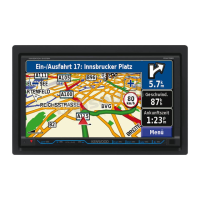
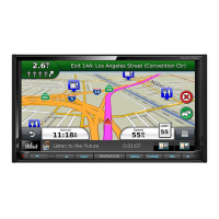
Displays GPS satellite status, signal level, and position data.

Dump Screen Operations

VICS Screen

FM Multisignal Screen

Beacon Information Screen

Location Information Screen

Disk Information Screen

Set Time GMT Screen

Engineering Diag Menu (Page2) Screen

HDD Information Screen

HF Voice Quality Parameter Screen

Bluetooth RF Test Screen

Reset Position Screen

Engineering Diag Menu (Page3) Screen

Connection Information Screen

Audio Diagnosis Menu Screen

Audio Information Screen

Vehicle Signal Information Screen

Touch Panel Adjust Screen

Touch Panel Check Screen

Hard Switch Check Screen

Speed Pulse Check Screen

Rear Camera Check Screen

Engineering Diag Menu (Page4) Screen

Dealer Setup Screen

Bluetooth Handfree Check Menu

Bluetooth Check Menu

Serial Communication Log Screen

Software Version Screen

Handfree Voice Quality Set Screen

Handfree Security Code Set Screen

System Adjustment Procedures

Power Supply Voltage Check

Check output voltage at the power supply unit (TP119).

Diversity Free-Run Frequency Adjustment (VR100)

Connect frequency counter and tune VR100 to set frequency.

TV and Stereo Separation Adjustment (VR300)

Apply TV antenna input and tune VR300 for minimum output amplitude.

TV S-meter Adjustment (VR302)

Apply TV antenna input and tune VR302 for output voltage.

System Interconnection Diagram

Parts List - Control Assy

Power Supply Unit Parts

Lists parts for the power supply unit.

Tuner Unit Parts

Lists parts for the tuner unit.

Synthesizer Unit Parts

Lists parts for the synthesizer unit.

Parts List - Synthesizer Unit (Continued)

Switch Unit Parts

Lists parts for the switch unit.

Electric Unit Parts

Lists parts for the electric unit.

Parts List - Synthesizer Unit (Continued)

Parts List - Synthesizer Unit (Continued)

Parts List - Synthesizer Unit (Continued)

Parts List - Synthesizer Unit (Continued)

Switch Unit Parts (Continued)

Lists parts for the switch unit.

Electric Unit Parts (Continued)

Lists parts for the electric unit.

Parts List - Synthesizer Unit (Continued)

Switch Unit Parts (Continued)

Lists parts for the switch unit.

Parts List - Electric Unit (Continued)

Electric Unit Parts (Continued)

Lists parts for the electric unit.

Parts List - Electric Unit (Continued)

Electric Unit Parts (Continued)

Lists parts for the electric unit.

DVD Unit Parts

Lists parts for the DVD unit.

Parts List - Electric Unit (Continued)

Electric Unit Parts (Continued)

Lists parts for the electric unit.

Parts List - Electric Unit (Continued)

Electric Unit Parts (Continued)

Lists parts for the electric unit.

Parts List - Electric Unit (Continued)

Electric Unit Parts (Continued)

Lists parts for the electric unit.

Switch Unit Parts (Continued)

Lists parts for the switch unit.

Parts List - Switch Unit (Continued)

Switch Unit Parts (Continued)

Lists parts for the switch unit.

DVD Unit Parts (Continued)

Lists parts for the DVD unit.

Parts List - DVD Unit (Continued)

DVD Unit Parts (Continued)

Lists parts for the DVD unit.

Parts List - DVD Unit (Continued)

DVD Unit Parts (Continued)

Lists parts for the DVD unit.

Parts List - DVD Unit (Continued)

DVD Unit Parts (Continued)

Lists parts for the DVD unit.

Parts List - DVD Unit (Continued)

DVD Mechanism Assembly Parts (DVS-8000V)

Lists parts for the DVS-8000V DVD mechanism assembly.

DVD Mechanism Assembly Parts (DVS-8521V)

Lists parts for the DVS-8521V DVD mechanism assembly.

Parts List - Capacitors

Chip Capacitor Details

Details dimensions, tolerances, and voltage ratings for chip capacitors.

Chip Resistor Details

Details dimensions, tolerances, and wattage for chip resistors.

Resistor Rating Wattage

Specifies wattage codes for chip resistors.

Related product manuals