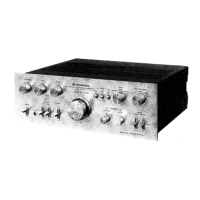
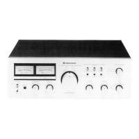
Do you have a question about the Kenwood KA-8011 and is the answer not in the manual?
Presents a functional block diagram of the amplifier's signal path.
Shows signal levels at various points in the circuit.
Procedure for removing and handling the unit's shaft.
Instructions for removing the power transistor and heat sink.
Steps for disassembling and accessing the power meter component.
Procedure for removing the rear panel and associated assemblies.
Instructions for disassembling the preamp section.
Equivalent circuit diagram for the TREBLE control section.
Equivalent circuit for achieving a flat TREBLE frequency response.
Graphs showing frequency responses of NF and RC sections.
Equivalent circuit for the TREBLE control when boosted.
Explanation of the BASS control circuit operation and its effects.
Equivalent circuit for achieving a flat BASS frequency response.
Equivalent circuit for decreasing the BASS control.
Equivalent circuit for boosting the BASS control.
Description of the integrated circuit used for protection functions.
Explanation of the zero-potential detection circuit.
Explanation of the overload detection circuit and its flip-flop mechanism.
Explanation of the line voltage detection circuit.
Explanation of the NOR gate logic and its role in power-on muting.
Explanation of the relay driver and voltage stabilizer circuit.
Equivalent circuit diagram for the HA12002 integrated circuit.
Procedure for adjusting the preamp offset voltage to zero.
Procedure for calibrating the power meter level.
Procedure for adjusting the bias current for the power amplifier section.
Details the amplifier's power output capabilities per channel.
Specifies the THD levels for different inputs and power outputs.
Details the frequency response across various input types and bandwidths.
Lists the input sensitivity and impedance for different signal sources.
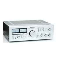
| Type | Stereo Integrated Amplifier |
|---|---|
| Power Output | 80 watts per channel into 8Ω (stereo) |
| Frequency Response | 5Hz to 100kHz |
| Input Sensitivity | 2.5mV (MM), 150mV (line) |
| Damping Factor | 50 |
| Output | 150mV (Line) |
| Speaker Load Impedance | 4Ω - 16Ω |