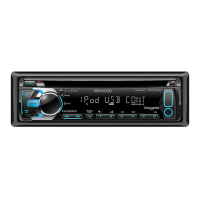
Do you have a question about the Kenwood KDC-316S and is the answer not in the manual?
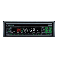
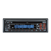
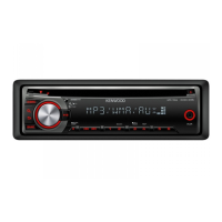
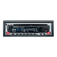
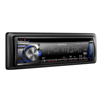
Identifies various knobs and buttons on the front panel.
Lists and illustrates external components like remote, screws, and cables.
Detailed listing of switch unit components, their functions, and conditions.
Detailed listing of electric unit components, their functions, and conditions.
Detailed explanation of microcomputer pins, I/O, and processing operations.
Instructions for accessing and performing unit adjustments and test modes.
Specific operations and sequences for various test modes.
Important considerations and notes for executing adjustments.
Diagram showing component placement on the electric unit's printed circuit board.
Diagram showing component placement on the switch unit's printed circuit board.
Diagram showing component placement on the switch unit's PCB (foil side).
Diagram showing component placement on the electric unit's PCB (foil side).
Component placement diagram for the CD player unit PCB (component side).
Component placement diagram for the CD player unit PCB (foil side).
Detailed electrical schematics for the main unit circuits (first section).
Detailed electrical schematics for the main unit circuits (second section).
Visual guide for disassembling the CD mechanism.
Visual guide for disassembling the main unit.
Comprehensive list of parts for the main unit.
Comprehensive list of parts for the switch unit.
Comprehensive list of parts for the electric unit.
Further listing of parts for the electric unit.
Comprehensive list of parts for the CD player unit.
Additional parts for the electric unit.
Further listing of parts for the CD player unit.
More parts for the CD player unit.
Comprehensive list of parts for the mechanism assembly.
Further parts for the mechanism assembly.
Performance details for FM, AM, and CD sections.
Amplifier power, tone controls, operating voltage, and dimensions.
| FM frequency range | 87.9MHz~107.9MHz |
|---|---|
| Usable sensitivity (S/N:30dB) | 9.3dBf (0.8µV/75Ω) |
| Quieting sensitivity (S/N:50dB) | 15.2dBf (1.6µV/75Ω) |
| FM frequency response | 30Hz~15kHz |
| FM signal-to-noise ratio | 70dB (MONO) |
| FM selectivity | ≥ 80dB(±400kHz) |
| FM stereo separation | 40dB(1kHz) |
| AM frequency range | 530kHz~1700kHz |
|---|---|
| AM usable sensitivity (S/N:20dB) | 28dB µ (25µV) |
| Laser diode | GaAIAs(λ=780nm) |
|---|---|
| Digital filter (D/A) | 8 Times Over Sampling |
| D/A converter | 1Bit |
| Spindle speed | 500~200(CLV) |
| CD frequency response | 10~20kHz(±1dB) |
| CD THD | 0.01%(1kHz) |
| CD S/N ratio | 96dB(1kHz) |
| Dynamic range | 93dB |
| Channel separation | 85dB |
| Preout level/load | 1800mV/10kΩ(CD/CD-CH) |
|---|---|
| Preout impedance | ≤ 600Ω |
| Maximum power | 45W×4 |
| Full bandwidth power | 22W×4 (at less than 1%THD) |
| Bass adjustment | 100Hz±10dB |
|---|---|
| Middle adjustment | 1kHz±10dB |
| Treble adjustment | 10kHz±10dB |
| Operating voltage | 14.4V (11V~16V allowable) |
|---|---|
| Current consumption | 10A |
| Installation size (W) | 182mm (7-3/16in) |
| Installation size (H) | 53mm (2-1/16in) |
| Installation size (D) | 157mm (6-3/16in) |
| Weight | 1.5kg (3.31lbs) |