EasyManua.ls Logo

Kenwood KDC-MP408U - User Manual

Kenwood KDC-MP408U
48 pages
Print Icon
To Next Page IconTo Next Page
Loading...
This product uses Lead Free solder.
This product complies with the
RoHS directive for the European market.
© 2008-2 PRINTED IN JA PAN
B53-0614-00
(
N
)
519
KDC-MP408U/MP438U/X492
KDC-MP5039U/MP5539U
KDC-W5041UA/W5041UG
KDC-W5141UAY/W5141UGY
KDC-W5541U/W5641UY
SERVICE MANUAL
CD RECEIVER
TDF SPARE-PANEL
MAIN UNIT NAME TDF PARTS No. TDF NAME
KDC-MP408U Y33-2920-62 TDF-MP84DT
KDC-MP438U Y33-2920-61 TDF-MP84D
KDC-MP5039U Y33-2920-64 TDF-MP5039U
KDC-MP5539U Y33-2920-63 TDF-MP5539U
KDC-W5041UA Y33-2920-66 TDF-W5041UA
KDC-W5041UG Y33-2920-67 TDF-W5041UG
KDC-W5141UAY Y33-2920-66 TDF-W5041UA
KDC-W5141UGY Y33-2920-67 TDF-W5041UG
KDC-W5541U Y33-2920-65 TDF-W5541U
KDC-X492
KDC-MP438U
KDC-MP408U
KDC-MP5539U
KDC-MP5039U
KDC-W5041U
KDC-W5641U
KDC-W5141U
KDC-W5541U
KDC-W5641UY Y33-2920-65 TDF-W5541U
KDC-X492 Y33-2920-60 TDF-84DX
Mounting hardware assy
(J21-9716-03)
Lever
(D10-7012-04) x2
* DC cord
(E30-6428-05)
* Screw set
(N99-1757-15)
* Escutcheon
(B07-xxxx-xx)
* Carrying case
(W01-xxxx-xx)
* DC cord
(E30-6671-05)
* Screw (4x16)
(N84-4016-48)
* Plastic cabinet assy
(A02-2755-13)
* Remote controller assy (RC-547)
(A70-2085-05)
Battery
(Not supplied)
* Depends on the model. Refer to the parts list.
KDC-MP408U : Panel assy (A64-4400-02)
KDC-MP5039U : Panel assy (A64-4402-02)
KDC-W5041Ux : Panel assy (A64-4404-02)
KDC-W5541U : Panel assy (A64-4403-02)
KDC-X492 : Panel assy (A64-4398-02)
KDC-MP438U : Panel assy (A64-4399-02)
KDC-MP5539U : Panel assy (A64-4401-02)
KDC-W5141Uxx : Panel assy (A64-4406-02)
KDC-W5641UY : Panel assy (A64-4405-02)
Question and Answer IconNeed help?

Do you have a question about the Kenwood KDC-MP408U and is the answer not in the manual?

Summary

Kenwood CD Receiver Service Manual Overview

Supported Models and Panel Assemblies

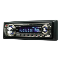
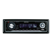
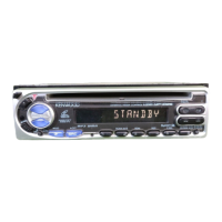
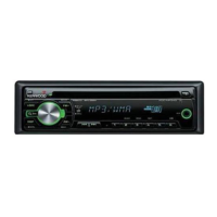
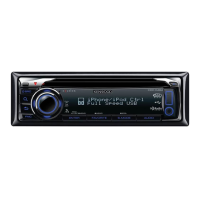
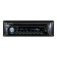
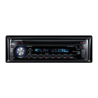
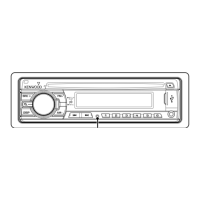
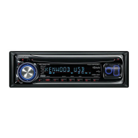
Lists CD receiver models and displays front panel assemblies for each unit.

Included Accessories and Parts

Identifies accessories like escutcheon, carrying case, and various cords provided with the unit.

Electrical System Block Diagrams

Electric Unit and System µ-COM Architecture

Illustrates the main electrical components and their interconnections, including the system microcontroller.

Switch Unit and Peripheral Interfaces

Details the switch unit and its connections to USB, remote control, and key inputs.

Component Descriptions: Electric Unit

Integrated Circuits and Transistors

Describes the function and operation of ICs and transistors within the electric unit.

Component Descriptions: System Units

Switch Unit and CD Player Components

Details the application and function of components in the switch and CD player units.

Microcomputer Terminal Descriptions: IC600

System µ-COM Pin Assignments and Functions

Details the pin functions, I/O, and operations for the system microcomputer IC600.

Microcomputer Terminal Functions

IC600 Pin Details and Operations

Provides further pin information and operational details for the IC600 microcomputer.

Microcomputer Pinout and Control Tables

IC600 Terminals and CD Motor Control

Completes IC600 terminal descriptions and includes CD motor control truth tables.

Test Mode: Entry and Clearing Procedures

Test Mode Operations and Default Settings

Explains how to enter, clear, and the default settings for the unit's test mode.

Test Mode: Special Displays and Data Logging

Standby Indicators and Data Recording Functions

Details special displays in standby mode and logging functions like ROM version and iPod status.

Test Mode: CD Information Display

Mechanism Errors and Data Logging

Explains how to view CD mechanism errors, load/ejection errors, and time code error counts.

Test Mode: Tuner and Adjustment Functions

Tuner Operations, RDS, and FST Modes

Covers tuner preset operations, K3I switching, RDS auto measurement, and FST adjustment mode.

Test Mode: CD Media Operations

CD-DA and Media File Navigation

Details test mode procedures for CD-DA, MP3, WMA, and AAC media, including track navigation.

Test Mode: Audio and System Settings

Audio Adjustments and Switching Modes

Explains audio adjustments, menu operations, backup measurement, PREOUT, and Dual Zone switching in test mode.

Test Mode: Data Clearing and Channel Switching

E2 PROM Data Clearing Procedures

Details methods for clearing CD mechanism, service, and DC offset error information from E2PROM.

Test Mode: Security Features and Registration

Security Code Management and Forced Power ON

Explains how to register and clear the security code, including forced power-on mode.

Test Mode: ROM Data Transfer Operations

ROM Data Transfer Procedures and Status

Details the steps for transferring ROM data between the front-end and mother unit, including status indicators.

ROM Data Transfer Processes Overview

Transfer Specifications and Data Content

Outlines the ROM data transfer process, specifications, and the types of data that can be copied.

ROM Data Transfer Operation Procedures

Step-by-Step Data Transfer Guide

Provides detailed operational steps for ROM data transfer scenarios, including READ and WRITE operations.

ROM Data Transfer Scenarios

Transferring ROM Correction Data

Details procedures for transferring ROM correction data, especially when applying new corrections.

ROM Data Transfer Operations (Continued)

Handling ROM Data Transfer Cases

Illustrates further steps and scenarios for ROM data transfer, including exiting the mode.

Switch Unit PC Board Layout

Component Placement Diagram (Component Side)

Shows the physical layout and component placement for the switch unit's printed circuit board.

Electric Unit PC Board Layout (Component Side)

Component Placement and References

Illustrates the component layout on the electric unit's printed circuit board, listing references.

Electric Unit PC Board Details (Component Side)

Component Identification and Addresses

Continues the PC board layout for the electric unit, showing component references and addresses.

Electric Unit PC Board Layout (Foil Side)

PCB Traces and Connections (Foil Side)

Displays the foil side layout of the electric unit's PCB, showing component traces and connections.

Electric Unit PC Board Details (Component Side) - Part 2

Additional Component Placement and References

Continues the component side view of the electric unit's PCB, listing component references.

CD Player Unit PC Board Layout (Component Side)

Component Placement and Identification

Shows the component layout and references for the CD player unit's printed circuit board.

CD Player Unit PC Board Layout (Foil Side)

PCB Traces and IC Locations (Foil Side)

Displays the foil side of the CD player unit's PCB, including component traces and IC locations.

Electric Unit Schematic Diagram (Section 1)

Power, Pre-out, and System µ-COM Connections

Illustrates power supply, pre-out signals, and connections to the system microcontroller.

Electric Unit Schematic Diagram (Section 2)

Muting Logic, IC Connections, and Signal Paths

Details muting logic, various IC connections, and signal paths within the electric unit.

Electric Unit Schematic Diagram (Section 3)

Power Control and I;O Interface Circuits

Covers power control circuits, I/O interfaces like USB, and tuner-related connections.

Electric Unit Schematic Diagram (Section 4)

Servo DSP and Audio Output Circuitry

Illustrates servo DSP functions, audio output circuits, and related component connections.

Electric Unit Schematic Diagram (Section 5)

Cautionary Notes and Component Schematics

Provides important cautionary notes and detailed schematic information for specific components.

Switch Unit Details and Model Configurations

PCB Layout and Model-Specific Data Table

Shows the switch unit PCB layout and a table detailing model and destination-specific configurations.

Switch Unit Component Information

Component Addresses and Safety Precautions

Lists switch unit component addresses and provides safety warnings regarding critical components and voltage measurements.

CD Player Unit Schematic Diagram (Section 1)

4 CH BTL Driver and IC Connections

Illustrates the 4CH BTL driver and details of various ICs within the CD player unit's schematic.

CD Player Unit Schematic Diagram (Section 2)

Optical Pickup and System IC Schematics

Details the optical pickup schematic and important system IC connections, with safety notes.

CD Mechanism Exploded View and Parts

Mechanical Component Identification and References

Provides an exploded view of the CD mechanism, identifying all mechanical parts by number.

Unit Exploded View and Parts Identification

Main Unit Component Identification and References

Displays an exploded view of the main unit, identifying external and internal components by number.

Parts List: Electric and Switch Units

Component Part Numbers and Destinations

Lists part numbers, descriptions, and destination codes for electric and switch unit components.

Parts List: Switch and CD Player Unit Components

CD Media Components and Specifications

Continues the parts list, detailing components for the switch unit and CD player mecha.

Parts List: CD Player and Electric Unit Components

Capacitors, Transistors, and Diodes

Lists specific capacitors, transistors, and diodes used in the CD player and electric units, with destination codes.

Parts List: Electric Unit Components (Resistors)

Resistor Part Numbers and Values

Details various resistors used in the electric unit, along with their part numbers and destinations.

Parts List: Electric Unit Components (Resistors Continued)

Resistor Specifications and Destination Codes

Lists more resistors for the electric unit, including part numbers, values, and applicable destinations.

Parts List: Electric Unit Components (Resistors Continued)

Resistor Values and Destination Information

Lists additional resistors for the electric unit, with their part numbers, values, and destination applicability.

Parts List: Electric Unit ICs and Transistors

Integrated Circuits and Transistors by Part Number

Details integrated circuits and transistors used in the electric unit, along with their part numbers and destinations.

Parts List: Unit and Mechanism Assembly Components

Front-end, Chassis, and Mechanism Parts List

Lists parts for the front-end unit, chassis, and the CD mechanism assembly, including fasteners.

Specifications: Destination K Models

Tuner, CD, USB, and Audio Performance Specs

Details specifications for FM/AM tuner, CD player, USB interface, audio output, and auxiliary input for 'K' destination models.

Specifications: Destination M and E Models

Performance Specifications for M and E Models

Provides detailed specifications for 'M' and 'E' destination models, covering tuner, audio, and general parameters.

Kenwood KDC-MP408U Specifications

General IconGeneral
DIN SizeSingle DIN
Detachable FaceYes
RMS Power Output22 watts
Peak Output50 watts
RMS Power Bandwidth20-20k Hz
Sub Preamp OutputsYes
Display TypeLCD
MP3 PlaybackYes
WMA PlaybackYes
AAC PlaybackYes
CD-R PlaybackYes
CD-RW PlaybackYes
ID3 Tag DisplayYes
USB InputYes
AUX InputYes
Remote ControlYes
TunerAM/FM
CD PlaybackYes
BluetoothNo
Power Output50 watts
TypeCar Receiver
Built-in DisplayYes
AM/FM Presets24 (18 FM, 6 AM)

Related product manuals