EasyManua.ls Logo

Kenwood KR-A4020 Service Manual

Kenwood KR-A4020
30 pages
To Next Page IconTo Next Page
Page #1 background imageLoading...
Page #1 background image
KR-A4020
iobsiebahc
SERVICE
MANUAL
©1990-3
PRINTED
IN
JAPAN
B51-4138-00
(S)
3223
Front
glass
Metallic
cabinet
Knob
(VOLUME
CONTROL)
2
2
‘(A01-
4
= 7
(B10-1076-03)
Panel*
{A01-1832-01)
Knob
(TUNING)
{K29-3597-04)
(K29-3893-04)
Knob
(SPEAKER)
Knob
(K27-2006-04)
Knob
(BASS,
TREBLE,
BALANCE)
ees
(K29-3892-03)
(K29-3894-04)
x3
Binding
post
Phono
jack
(2P)
Lock
terminal
board
(8P)
AC
outlet?
AC
power
cord*
(NO8-0128-35)
(E13-0235-05)
(E20-0823-05)
(E03-)
{E03-)
Slide
switch
Lock
terminal
board"
Phono
jack
(8P)
Slide
switch
ealsetsi
te)
Power
cord
bushing
(E20-)
(E13-0820-05)
(S31-2136-05)
(J42-0083-05)
*
Refer
to
parts
list
on
page
28.
Question and Answer IconNeed help?

Do you have a question about the Kenwood KR-A4020 and is the answer not in the manual?

Kenwood KR-A4020 Specifications

General IconGeneral
TypeStereo Receiver
Tuning RangeFM, MW
Speaker Impedance8Ω to 16Ω
Frequency Response20Hz to 20kHz
Input Sensitivity2.5mV (MM), 150mV (line)
Signal to Noise Ratio75dB (MM)
Output150mV (line)

Summary

Front Panel Controls and Indicators

Front Panel Controls

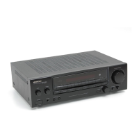
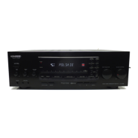
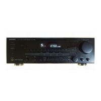
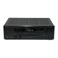
Identifies and describes the various knobs, switches, and keys on the front panel.

Display Section and Indicators

Details the digital display and status indicators on the front panel.

System Connections

Disassembly and Repair Procedures

Front Panel and Sub-panel Removal

Step-by-step guide for removing the front and sub-panels of the unit.

Main PC Board and Chassis Removal

Instructions for removing the main PC board and the repairing chassis.

Block Diagram

Circuit Description and Analysis

Microprocessor and Key Matrix Connections

Details the microprocessor connections and key input matrix.

Initial Settings and Test Modes

Explains initial setup procedures and how to enter test modes.

Component Functionality and Pinouts

Describes the function of various ICs, pins, and circuit elements.

IC Truth Tables and Logic

Explains the truth tables and logic for key integrated circuits.

Tuning and Adjustment Procedures

Wiring Diagram

Exploded View and Parts Identification

Parts List

Specifications

Related product manuals