Do you have a question about the Kenwood KR-A5010 and is the answer not in the manual?
How to select characters for station name display.
Guide to memorizing station frequencies and names.
Procedure to modify existing preset station names and frequencies.
Explains various control keys like CD, Tuner, Tape, Input selectors.
Details on power, volume, equalizer, and surround control keys.
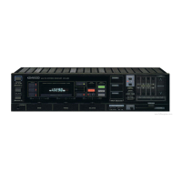
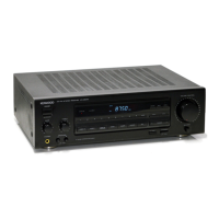
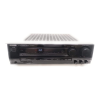
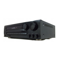
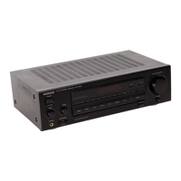
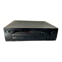
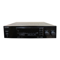
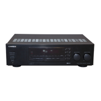
Overview of individual components and their functions.
Describes the tuner section and the microprocessor functions.
Explains the function of each terminal on the circuit boards.
Describes the initial settings for the microprocessor and system.
Details the initial state of microprocessor output ports.
Procedure to enter and exit the test mode.
Visual representation of muting signal timing during operations.
Details on main amplifier and FM MPX ICs.
Equivalent block diagram and terminal functions for the FM MPX IC.
Block diagram and terminal description for the PLL IC.
Adjustment procedures for the FM receiver section.
Adjustment procedures for the AM receiver section.
Layout of components on the main circuit board.
Layout of traces on the reverse side of the circuit board.
| tuning frequency range | 87.5 MHz- 108 MHz |
|---|---|
| antenna impedance | 300 ohms balanced & 75 ohms unbalanced |
| sensitivity (mono) | 11.2 dBf (2.0 nV at 300 ohms) |
| sensitivity (stereo) | 25 pV |
| signal-to-noise ratio (mono) | 78 dB |
| signal-to-noise ratio (stereo) | 72 dB |
| power consumption | 2.0A USA Model/150 W Others |
|---|---|
| dimensions | 440 (W) X 133 (H) X 284 (D) mm |
| weight | 6.0 kg (13.2 lb) |
| rated power output | 60 watts per channel |
|---|---|
| total harmonic distortion (mono) | 0.1% |
| total harmonic distortion (stereo) | 0.45% |
| input sensitivity/impedance (phono MM) | 2.5 mV/47 kohms |
| input sensitivity/impedance (CD, TAPE, VIDEO) | 150 mV/47 kohms |
| frequency response (phono MM) | 30 Hz to 15 kHz |
| frequency response (CD, TAPE, VIDEO) | 10 Hz to 70 kHz |
| stereo separation | 40 dB at 1 kHz |
| signal-to-noise ratio (IHF-A) | 70 dB |
|---|---|
| tuning range | 530 kHz- 1.610 kHz |
| usable sensitivity | 10 pV (320 uV/m) |