Do you have a question about the Kenwood KR-V8020 and is the answer not in the manual?
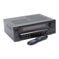
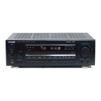
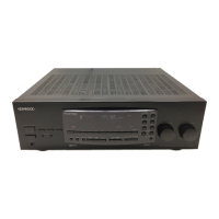
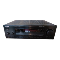
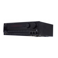
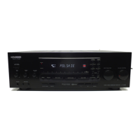
Identification of key components on the front panel.
Identification of key connectors on the rear panel.
Identification of other external parts like feet and cords.
Identification of FM and AM antennas and adaptors.
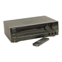
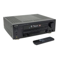
Identification of batteries and remote control unit.
Guidance on connecting audio components to the unit.
Guidance on connecting speaker systems to the unit.
Explanation of the remote control buttons and their functions.
Explanation of different operating modes for the remote control.
Step-by-step guide to disassembling the front panel.
Step-by-step guide to removing main PC boards.
Steps to remove the X05-(A/2) board.
Steps to install the X05-(A/2) board.
Steps to remove the X08-(A/7) board.
Steps to install the X08-(A/7) board.
Diagram showing audio and tuner signal paths.
Diagram showing digital delay and amplifier signal paths.
Lists and describes components in the tuner unit.
Lists and describes components in the pre-amplifier unit.
Lists and describes components in the audio unit.
Lists and describes components in the display unit.
Lists and describes components in the main amplifier unit.
Diagram of main microprocessor connections to peripherals.
Diagram of display microprocessor connections.
Explanation of each terminal on the main microprocessor.
Describes the key matrix inputs for the main microprocessor.
Explains the port status for video functions.
Details pin assignments for port extension ICs.
Explanation of IC5 terminals for relay and volume control.
Explanation of IC6 terminals for display control.
Details assignments for TC9164N, TC9163N, and TC9162N ICs.
Details port assignment for the LM7001 PLL IC.
Explains control for LC7522 and LC7565 ICs.
Explains control for TC9176P IC.
Explanation of terminals for µPD7537ACU-220 (IC2).
Describes the key matrix for the first sub microprocessor.
Detailed explanation of IC2 terminals (RESET, CL1, CL2, etc.).
Explanation of terminals for µPD7537ACU-220 (IC3).
Describes the key matrix for the second sub microprocessor.
Detailed explanation of IC3 terminals (RESET, CL1, CL2, etc.).
Describes the initial setting function of the unit.
Describes how to enter and exit test mode.
Details functions active in test mode (tuner frequencies, LEDs, volume).
Explanation of the analog converter circuit for noise reduction.
Lists key features of the µPC1571C IC.
Graph showing input/output characteristics of the IC.
Shows standard application circuit examples.
Circuit diagram for compressor application.
Circuit diagram for expander operation.
Theoretical values for headroom and noise level.
Overview of the YM3428 digital delay IC.
Explanation of the digital delay function and processing.
Terminal connection diagram for YM3428.
Block diagram of the digital delay system.
Explanations for YM3428 IC terminals.
Overview of the LA2730 IC for Dolby B noise reduction.
Table showing decode characteristics.
Terminal connection diagram for LA2730.
Block diagram for the noise reduction circuit.
Covers detector, distortion, VCO, separation, and tuning level adjustments.
Covers band edge, RF alignment, IF transformer, and tuning level adjustments.
Covers idle current adjustment.
Tuning detector adjustment steps.
Tuning distortion adjustment for mono.
Tuning voltage controlled oscillator adjustment.
Tuning distortion adjustment for stereo.
Tuning separation adjustment.
Tuning level adjustment.
AM band edge adjustment (low).
AM band edge adjustment (high).
AM RF alignment adjustments.
AM IF transformer adjustment.
AM tuning level adjustment.
Audio section idle current adjustment.
FM detector adjustment.
FM mono distortion adjustment.
FM voltage-controlled oscillator adjustment.
FM stereo distortion adjustment.
FM separation adjustment.
FM tuning level adjustment.
AM band edge adjustment (low).
AM band edge adjustment (high).
AM RF alignment adjustments.
AM IF transformer adjustment.
AM tuning level adjustment.
Audio section idle current adjustment.
Wiring connections for the tuner unit.
Wiring connections for the audio unit.
Wiring connections for the pre-amplifier unit.
Wiring connections for the display unit.
Component layout for the pre-amplifier board.
Layout for surround speaker connections.
Component layout for the main amplifier board.
Layout for speaker connections.
Component layout for the display unit board.
Component layout for main control keys and volume.
Component layout for the volume control section.
Component layout for the audio unit board.
Component layout for the tuner unit board.
Component layout for the main amplifier unit board.
Schematic diagram for the tuner unit.
Schematic diagram for the pre-amplifier unit.
Schematic diagram for the audio unit.
Schematic diagram for the digital delay unit.
Schematic diagram for the main amplifier unit.
Schematic diagram for control circuits.
Schematic diagram for the main microprocessor.
Schematic diagram for sub microprocessors.
Schematic diagram for driver circuits.
Schematic diagram for the audio circuits.
Schematic diagram for system control circuits.
Schematic diagram for the display unit.
Schematic diagram for remote control interface.
Detailed schematic of the tuner unit.
Schematic diagram of the front-end circuit.
Schematic showing signal paths in the audio unit.
Schematic showing signal paths in system control.
Exploded view of the main unit frame and front parts.
Exploded view of internal unit assemblies.
Exploded view of front panel controls and buttons.
Exploded view of rear panel connectors and jacks.
Parts list for chassis, panels, glass, and accessories.
Parts list for the tuner unit.
Parts list for capacitors and inductors in the pre-amp unit.
Parts list for resistors and switches in the pre-amp unit.
Parts list for other components in the pre-amp unit.
Parts list for capacitors and fuses in the display unit.
Parts list for connectors and jacks in the display unit.
Parts list for resistors and potentiometers.
Parts list for diodes and switches.
Parts list for audio and signal processing ICs.
Parts list for microprocessor and driver ICs.
Parts list for capacitors C49 through C82.
Parts list for capacitors C83 through C102.
Parts list for capacitors C103 through C183.
Parts list for connectors and fuses.
Parts list for capacitors C184 through C54.
Parts list for transistors Q1 through Q15.
Parts list for diodes D1 through D68.
Parts list for specific ICs.
Parts list for transistors Q1 through Q15.
Parts list for the display unit components.
Parts list for resistors R39 through R64.
Parts list for diodes D1 through D68.
Specifications for front and rear power output.
Specifications for maximum continuous output power.
Specifications for video inputs and outputs.
FM tuner frequency range and sensitivity specifications.
FM tuner S/N ratio and distortion specifications.
FM tuner frequency response and separation specifications.
AM tuner tuning range and sensitivity specifications.
AM tuner S/N ratio and distortion specifications.
AM tuner selectivity specifications.
Specifications for power consumption and unit dimensions.
Specification for the net weight of the unit.
| Total Harmonic Distortion | 0.08% |
|---|---|
| Speaker load impedance | 4 - 16 ohms |
| Dimensions | 17.1 x 5.5 x 14.9 inches |
| Weight | 22.5 lbs |
| Type | Receiver |
| Tuning range | FM |
| Power Output | 100 W per channel (8 ohms) |
| Frequency Response | 20Hz to 20kHz |
| Input Sensitivity | 2.5mV (MM), 200mV (line) |
| Signal-to-Noise Ratio | 100dB (line) |
| Speaker Impedance | 8Ω to 16Ω |
| Video Connections | Composite |