EasyManua.ls Logo

Kenwood KRC-218 User Manual

Kenwood KRC-218
19 pages
To Next Page IconTo Next Page
Page #1 background imageLoading...
Page #1 background image
CASSETTE RECEIVER
KRC-208S/218
SERVICE MANUAL
© 2000-1 PRINTED IN KOREA
B51-7586-00 (K) 1787
KRC-268/288
KRC-28MR
KRC-28MR (K)
PLASTIC CABINET ASSY
(A02-1486-13)
LEVER
(D10-3031-04) x2
MOUNTING HARDWARE ASSY
(J21-9491-03)
DC CORD
(E30-xxxx-xx)
(Refer to the parts list.)
CD/MD-CHANGER CONTROL
KRC-208S
CD/MD-CHANGER CONTROL
KRC-28MR
KRC-268
KRC-208S (K)
KRC-218 (K)
KRC-268 (M)
STAY
(J54-0606-04)
SCREW SET
(N99-1610-15)
(Except KRC-28MR)
SCREW SET
(N99-1632-05)
KRC-218
CD/MD-CHANGER CONTROL
KRC-288
KRC-288 (M)
AUD
1
23456
CLK
ATT
SRC
PWR
OFF
AME ADJAUTO
SCAN RDM REP T.C/D.SCN M.RDM
LOUD
DISC
CRSC
A.ADJ
FM
AM
FF
REW
PR OG
AUD
1
23456
CLK
ATT
SRC
PWR
OFF
AME ADJAUTO
SCAN RDM REP T.C/D.SCN M.RDM
LOUD
DISC
CRSC
A.ADJ
FM
AM
FF
REW
PR OG
AUD
1
23456
CLK
ATT
SRC
PWR
OFF
AME ADJAUTO
T.CALL
LOUD
CRSC
A.ADJ
FM
AM
FF
REW
PR OG
AUD
1
23456
CLK
ATT
SRC
PWR
OFF
AME ADJAUTO
T.CALL
LOUD
CRSC
A.ADJ
FM
AM
FF
REW
PR OG
AUD
1
23456
CLK
ATT
SRC
PWR
OFF
AME ADJAUTO
SCAN RDM REP T.C/D.SCN M.RDM
LOUD
DISC
CRSC
A.ADJ
FM
AM
FF
REW
PR OG
40%
Question and Answer IconNeed help?

Do you have a question about the Kenwood KRC-218 and is the answer not in the manual?

Kenwood KRC-218 Specifications

General IconGeneral
BrandKenwood
ModelKRC-218
CategoryCar Receiver
LanguageEnglish

Summary

KRC Series Service Manual Introduction

Model Identification and Front Panel Layouts

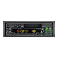
Identifies the KRC series models and shows their front panel configurations.

Block Diagram

System Block Diagram Overview

Visual representation of the unit's main functional blocks and their interconnections.

Component Description

Synthesizer Unit Component Details

Detailed description of components found in the synthesizer unit.

Circuit Description

IC1: μ-COM Circuit Details

Explanation of the μ-COM IC's ports, functions, and operating conditions.

Test Mode

Test Mode Entry and Audio Adjustment

Instructions for entering test mode and performing audio adjustments.

Mechanical Adjustments

Head Angle Adjustment Procedure

Procedure to adjust the head angle for optimal tape performance.

PC Board Layouts: Synthesizer Unit

Component Side View

Diagram showing component placement on the synthesizer unit's component side.

PC Board Layouts: Synthesizer Unit

Foil Side View

Diagram showing component placement on the synthesizer unit's foil side.

PC Board Layouts: Switch Unit

Component Side View

Diagram showing component placement on the switch unit's component side.

Schematic Diagrams

Main Circuit Schematic

Detailed circuit diagram showing electronic components and connections.

Schematic Diagrams

Component Cross-Reference Table

Table correlating model numbers with specific components and ICs.

Exploded View: Mechanism

Mechanism Assembly Details

Exploded view of the cassette mechanism showing assembly of parts.

Exploded View: Unit

Unit Assembly Details

Exploded view of the main unit showing assembly of parts.

Exploded View: TDF

TDF Assembly Details

Exploded view of the Tape Drive Function unit showing assembly of parts.

Parts List

Parts for KRC Models and Hardware

List of parts specific to KRC models and general hardware components.

Parts List

Component Parts: Resistors, Capacitors, Diodes

Detailed list of resistors, capacitors, and diodes with part numbers.

Parts List

Component Parts: ICs and Transistors

Detailed list of integrated circuits and transistors with part numbers.

Parts List

Component Parts: Modules and Hardware

List of electronic modules and hardware components.

Specifications

Model Specifications Comparison

Comparison of technical specifications across different KRC receiver models.

Related product manuals