EasyManua.ls Logo

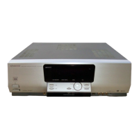
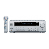
Kenwood KRF-V4060D Service Manual

Kenwood KRF-V4060D
36 pages
To Next Page IconTo Next Page
Page #1 background imageLoading...
Page #1 background image
70%
AUDIO-VIDEO SURROUND RECEIVER
© 2002-2 PRINTED IN KOREA
B51-5783-00 (K/K) 3526
POWER
STANDBY
DIMMER
SPEAKERS ON
OFF
PHONES
CINEMA EQ
LISTEN MODE
INPUT MODE BAND AUTO MEMORY
DSP DTS
DOLBY DIGITAL
SOUND
SET UP
MULTI CONTROL INPUT SELECTOR
DOWN
MUTE
UP
VOLUME CONTROL
ON OFF
ON
STANDBY
Knob *
(K29-)
Knob(BUTTON) *
(K27-)
AUX
VOLTAGE
SELECTOR
AC110V-120V / 220V-240V~
50 / 60Hz
SWITCHED
TOTAL 90W MAX.
GND
VIDEO 1
OUT
AC OUTLETS
SPEAKERS
GND
AM
ANTENNA
FM
75
VIDEO
SURROUND
SPEAKERS
(8-16)
CENTER
SPEAKER
(8-16)
FRONT
SPEAKERS
(8-16)
AC 220-
240V~
AC 110-
120V~
VIDEO 2
COAXIAL
DVD
DIGITAL IN
DE-
EMPHASIS
CHANNEL
SPACE
SYSTEM
CONTROL
75µs
AM 10kHz
FM 100kHz
50µs
AM 9kHz
FM 50kHz
VIDEO 2
IN
DVD
IN
VIDEO 1
IN
MONITOR
OUT
SUB WOOFER
PRE OUT
PLAY IN
VIDEO 2
DVDREC OUT PLAY IN
MD / TAPE
CD / DVD
AUDIO
GRAYWHITE GREEN BLUERED
L C
R
L
R
REC OUT PLAY IN
VIDEO1
CD / DVD
OPTICAL
L
R
+
-
+
-
Front glass *
(B10-)
* Refer to parts list on page 21.
KRF-V4060D/V4060DE/V4060DE-S/V4060D-S
SERVICE MANUAL
Metallic cabinet *
(A01-)
AC power cord bushing
(J42-0083-05)
AC power cord *
(E30-)
Illust. is KRF-V4060D.
KRF-V5060D/V5060DE/V5060D-S/V5560D/V5560D-S
VR-605/615
Phone jack
(E11-0271-05)
Knob *
(K29-)
Panel *
(A60-)
Knob *
(K29-)
Knob *
(K29-)
Knob *
(K29-)
Knob *
(K29-)
Tuner ass'y *
(W02-)
Miniature phone jack
(E11-0293-05)
Optical receiving module
(W02-2802-05)
Pin jack
(E63-1080-05)
AC outlet *
(E03-)
Pin jack
(E63-1254-05)
Pin jack
(E63-1255-05)
Pin jack
(E63-1256-05)
Pin jack
(E63-1258-05)
Pin jack
(E63-1146-05)
Lock terminal board
(E70-0156-05)
Lock terminal board
(E70-0155-05)
Pin jack *
(E63-)

Other manuals for Kenwood KRF-V4060D

Question and Answer IconNeed help?

Do you have a question about the Kenwood KRF-V4060D and is the answer not in the manual?

Kenwood KRF-V4060D Specifications

General IconGeneral
Power Output100 watts per channel into 8Ω (stereo)
Frequency Response10Hz to 70kHz
Total Harmonic Distortion0.7%
Input Sensitivity200mV (line)
Signal-to-Noise Ratio95dB (line)
Dimensions440 x 143 x 303mm
Weight8.5kg
Digital inputsCoaxial, Optical
Tuning rangeFM
Video Connectionscomposite
Input Sensitivity/Impedance200mV
Speaker load impedance8Ω to 16Ω
Speaker Impedance8Ω to 16Ω

Summary

Cautions

Resetting the Microcomputer

Procedure to reset the microcomputer for normal operation.

Memory Back Up Function

Details on data deleted when power is disconnected for extended periods.

Circuit Description

Model and Tuner Destination

Details on model discrimination and tuner destination settings.

Tuner Preset Memory

List of preset radio frequencies.

Test Mode Procedures

Methods for entering, cancelling, and using test modes.

Microcomputer Description

Details of the microcomputer and its pin functions.

IC Pin Descriptions

Detailed pin descriptions for various integrated circuits.

FL Driver Description

Pin description for the FL driver IC.

Power Amplifier Circuits

Details on front, center, surround, and SW amplifier ICs.

Digital Audio Decoder Description

Pin description for the digital audio decoder IC.

PC Board Layout

Schematic Diagram

Safety and Measurement Precautions

Important safety notes and measurement guidelines for service.

Exploded View

Parts List

Specifications

US/Canada Audio Specifications

Power, distortion, frequency response, and input/output specs for US/Canada models.

Digital, Video, and Tuner Specifications

Details on digital audio, video, FM, and AM tuner performance.

General and Physical Specifications

Power consumption, dimensions, and weight of the unit.

Related product manuals