EasyManua.ls Logo

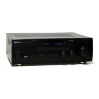
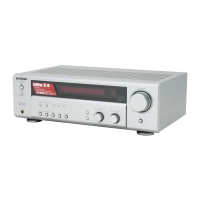
Kenwood KRF-V5010 Service Manual

Kenwood KRF-V5010
40 pages
To Next Page IconTo Next Page
Page #1 background imageLoading...
Page #1 background image
AUDIO VIDEO SURROUND RECEIVER
KRF-V5010/V5010E/V5010W/
KRF-V6010/V6010E/V6010W/
KRF-V7010/V7010E/V7010W/
VR-205/207/255/257
SERVICE MANUAL
© 1998-4/B51-5425-00 (K/K) 3484
A
SPEAKERS
B
BASS BOOST
VIDEO 2/
MONITOR
SOURCE
DIRECT
LISTEN MODE
SOUND
SETUP
MULTI CONTROL INPUT SELECTOR
VOLUME CONTROL
DOWN
UP
STANDBY
AV SURROUND RECEIVER
ON / STANDBY
PHONES
- ON OFF
POWER
PTY
TA/NEWS DISPLAY
BAND
AUTO
MEMORY
REC OUT
PHONO CD MD / TAPE
VIDEO 2/MONITOR VIDEO 1
PLAY IN PLAY IN PLAY INREC OUT
SUB
WOOFER
L
R
VIDEO 2
SURROUND
FRONT
MONITOR
VIDEO IN
DVD 5CH INPUT
VIDEO OUT
FM
75
GND
AM
ANTENNA
CABLE READY (TV)
(ƒ)
SYSTEM CONTROL
SL16
(XS8)
SUBWOOFER
SURROUND
PRE OUT
CENTER
CENTER
6CH INPUT
VIDEO 1
VIDEO 2
L
R
CENTER SPEAKER
(8~16)
FRONT SPEAKERS
(8~16)
++
--
R
A
L C
SURROUND SPEAKERS
(8~16)
FRONT SPEAKERS
(8~16)
L
R
+
+
--
+
+
--
L
R
B
KENWOOD badge
(B43-0302-04)
Knob*
(K29-)
Phone jack*
(E11-)
Knob*
(K29-)
Knob*
(K29-)
Knob*
(K27-)
Foot*
(J02-)
Metallic cabinet*
(A01-)
Phono jack (4Px2)
(E63-0172-05)
Phono jack
(E63-1019-05)
Phono jack
(E63-1018-05)
Lock terminal board*
(E70-)
Phono jack
(E63-1015-05)
Lock terminal board*
(E70-)
AC outlet*
(E03-)
AC power cord*
(E30-)
AC power cord bushing
(J42-0083-05)
Lock terminal board
(E70-0080-05)
RF coaxial cable receptacle
(E04-0026-05)
Front glass*
(B10-)
Knob*
(K29-)
Knob*
(K29-)
* Refer to parts list on page 33.
Miniature phone jack(2P)
(E11-0347-05)
Slide switch
(S62-0034-05)
Phono jack (3Px2)
(E63-1017-05)
Phono jack (6P)
(E63-0173-05)
KRF-V5010(K) COVER( 98.12.9 12:21 y[W 2
w
w
w
.
x
i
a
o
y
u
1
6
3
.
c
o
m
Q
Q
3
7
6
3
1
5
1
5
0
9
9
2
8
9
4
2
9
8
T
E
L
1
3
9
4
2
2
9
6
5
1
3
9
9
2
8
9
4
2
9
8
0
5
1
5
1
3
6
7
3
Q
Q
TEL 13942296513 QQ 376315150 892498299

Other manuals for Kenwood KRF-V5010

Question and Answer IconNeed help?

Do you have a question about the Kenwood KRF-V5010 and is the answer not in the manual?

Kenwood KRF-V5010 Specifications

General IconGeneral
BrandKenwood
ModelKRF-V5010
CategoryStereo Receiver
LanguageEnglish

Summary

Disassembly for Repair Procedures

Microprocessor Pin Descriptions (Part 1)

Microprocessor Pin Descriptions (Part 2)

Details the function of microprocessor pins 31 through 63, including tuner, relay, and mute controls.

Microprocessor Pin Descriptions (Part 3)

Adjustment Procedures

FM Section Adjustments

Details the adjustments for discriminator, tuning level, and distortion in the FM section.

PC Board Layout Diagrams - Tuner and Power Units

Tuner Unit PC Board Layout

Displays the component placement for the Tuner Unit, indicating various ICs, transistors, and resistors.

Schematic Diagram - Tuner Unit

Tuner Unit Circuit Details

Explains the circuit operation and component functions within the Tuner Unit.

Schematic Diagram - Power and Amplifier Units

Main Amplifier Unit Schematic

Details the schematic diagram for the Main Amplifier Unit, showing audio output stages and speaker connections.

Schematic Diagram - Input and Control Circuits

Control and Microprocessor Interface Schematics

Illustrates the schematics for the microprocessor interface and control signal routing.

Schematic Diagram - Tuner and SAP Unit

Exploded View of Receiver Unit

Exploded View - Main Chassis Components

Details the exploded view of the main chassis, including panels, heatsinks, and power supplies.

Parts List - VR-206/207/257/KRF-V7010 Models

Parts List - Model Variations (Knobs, Transformers)

Parts List - KRF-V6010 Series Components

Parts List - Power Supply and Tuner Components

Power Supply Unit Components List

Lists capacitors, diodes, transistors, and ICs used in the power supply unit.

Parts List - Tuner Unit Components (Part 1)

Tuner Unit Capacitors and Transistors List

Details various capacitors and transistors used in the tuner unit.

Parts List - Tuner Unit Components (Part 2)

Tuner Unit Resistors List

Lists various resistors used in the tuner unit, classified by type and value.

Parts List - Tuner Unit Components (Part 3)

Tuner Unit Transistors List

Lists various transistors used in the tuner unit, specifying their type and destination.

Parts List - Tuner Unit Components (Part 4)

Parts List - Tuner Unit Components (Part 5)

Parts List - Audio Unit Components (Part 1)

Parts List - Audio Unit Components (Part 2)

Parts List - Audio Unit Components (Part 3)

Parts List - Audio Unit Components (Part 4)

Parts List - Model and Destination Summary

Specifications - Audio and Video (USA/Canada)

Specifications - Audio and Tuner (Europe)

Specifications - Audio and Tuner (Other Countries)

Related product manuals