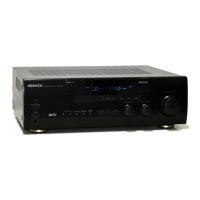
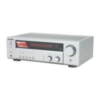
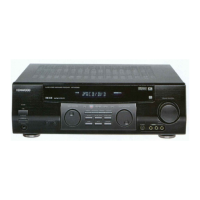
Do you have a question about the Kenwood KRF-V5070D and is the answer not in the manual?
Introduction to the KENWOOD Audio-Video Surround Receiver Service Manual.
Identification of front and rear panel components and their part numbers.
List of accessories supplied with the receiver, including remote controls and antennas.
Procedure for resetting the microcomputer and information on memory backup function.
Diagram illustrating the interconnection of various system components and boards.
Component layout diagram for the PC Board X25-6520-12.
Component layout diagram for PC Board X08-3130-10 (Side A).
Component layout diagram for PC Board X08-3130-10 (Side B).
Component layout diagram for PC Board X08-3230-10 (Side A).
Component layout diagram for PC Board X08-3230-10 (Side B).
Component layout diagram for PC Board X08-4780-10 (Side A).
Component layout diagrams for PC Boards X14-7650-10 and X14-7660-10.
Schematic diagram for the Digital Audio section.
Schematic diagram for power supply and system control circuits.
Schematic diagram detailing analog and DSP processing circuits.
Schematic diagram for audio output and tuner sections.
Schematic diagram for front panel controls and display circuitry.
Schematic diagram of the power transformer and AC outlet connections.
Schematic diagram for remote control interface and display circuits.
Schematic diagram for front panel buttons and selector circuitry.
Schematic diagram for DSP and input/output interface circuits.
Exploded view illustrating the assembly of the receiver unit and its components.
List of miscellaneous parts, including cabinets, screws, and panel components.
List of knobs, cables, power adapters, and transformers.
List of capacitors (C series) with part numbers and specifications (Part 1).
List of resistors (R series) and diodes (D series) with specifications.
List of integrated circuits (IC series) and their functions.
List of capacitors (C series) and connector parts.
List of resistors, diodes, and switches with part numbers.
List of integrated circuits (IC series) and transistors.
List of capacitors (C series) with part numbers and specifications (Part 1).
List of capacitors (C series) with part numbers and specifications (Part 2).
List of capacitors (C series) and connector parts.
List of fuses, coils, and diodes with specifications.
List of transistors and the crystal resonator.
List of connectors (CN series) and switches (S series).
Audio performance specifications for USA and Canada models.
Specifications for Digital Audio, Video, and S-Video inputs/outputs.
FM and AM tuner performance specifications.
General specifications including power consumption, dimensions, and weight.
Contact information for KENWOOD Corporation and its international subsidiaries.
| Power Output | 100W per channel (8 ohms) |
|---|---|
| Channels | 5.1 |
| Frequency Response | 20Hz - 20kHz |
| Dimensions | 17.1 x 6.3 x 14.2 inches |
| Weight | 20.1 lbs |
| Total harmonic distortion | 0.08% |
| Speaker load impedance | 8 ohms |
| Total Harmonic Distortion (THD) | 0.08% |
| Inputs | 4 x analog audio, 1 x phono (MM), 1 x Digital Optical, 1 x Digital Coaxial |
| Outputs | subwoofer pre-out |
| Tuning range | FM |
| Input sensitivity | 2.5 mV (phono) |
| Digital inputs | 1 x Coaxial |
| Input Sensitivity/Impedance | 200mV (line) |
| Speaker Impedance | 8 ohms |
| AM Sensitivity | 30 µV |


 Loading...