KRF-X7775D/X7775D-S/VR-5080/5090
7
CIRCUIT DESCRIPTION
5.Test Mode
5-1 Setting Method of the Test Mode
•Turn on the power supply while pressing the "INPUT SELECTOR DOWN" key, to make a set in test mode.
5-2 Canceling the Test Mode
•The system is initialized and the test mode is cancelled if unplug the AC power cord from an AC power wall outlet.
5-3 Contents of the Test Mode
✽ The following operation is available when the FL is all lighting up mode only.
Key Operation Display
SOUND Set up the RF frequency to428MHz. RF BAND
LISTEN MODE Set up the RF frequency to422MHz. RF BAND
THX Indicated the tuner destination in the FL. EX. TYPE E1
MEMORY Changed the dimmer off/1/2 cyclically. ALL FL Light ON
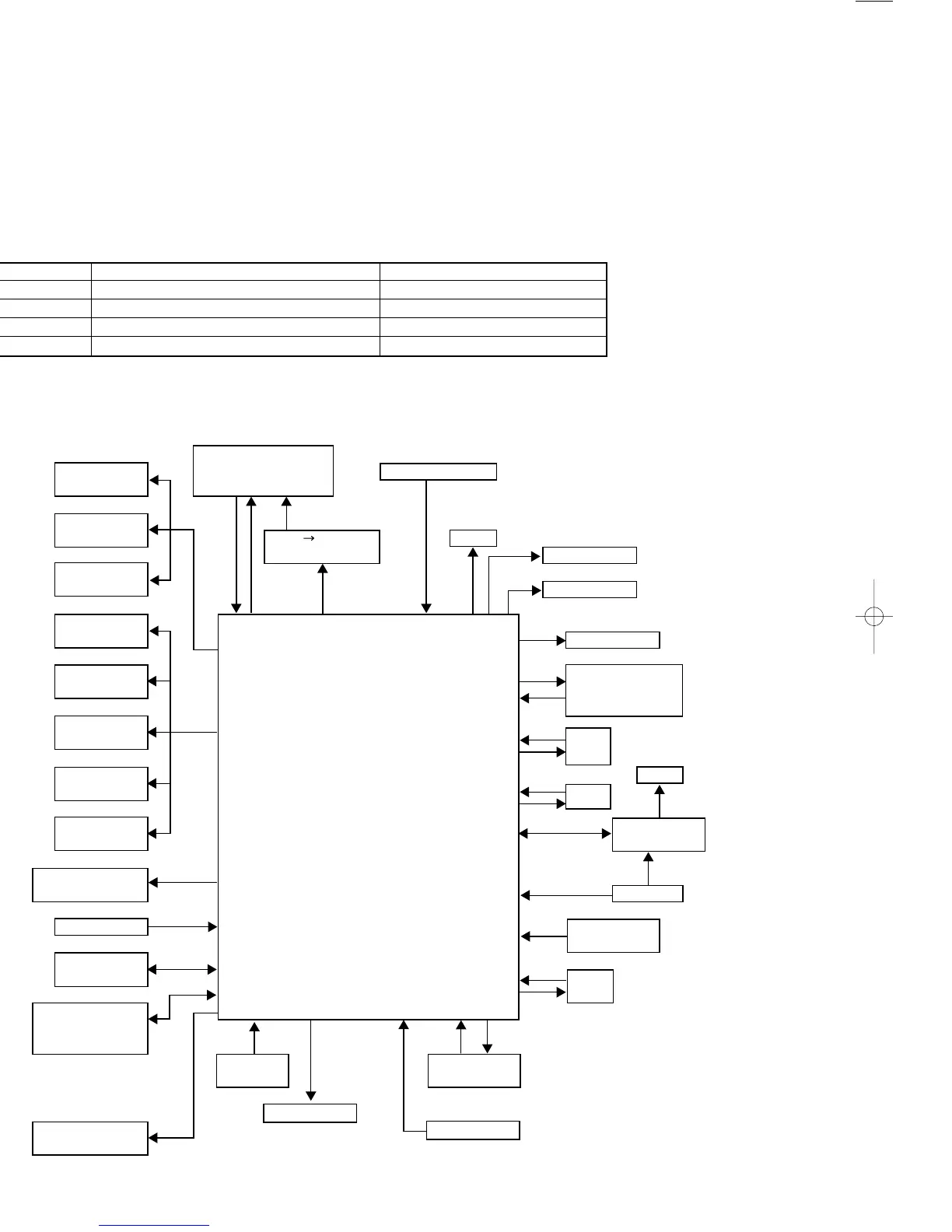
6. Main Microcomputer: uPD784217A516 (X13, IC3)
6-1 Main Microcomputer Periphery block diagram
X13,IC6
X11(IC2/21) LCD Remote Cont.
Selector IC
Transmitter IC
Protection
NJU7312AM
uPD17215GF
X11(IC3/22/24)
Selector IC X13,IC5
NJU7313AM Serial
Parallel Fan X07,K6
X11,IC23 TC74HC164AF PWR Relay
Selector IC X07,K1~k4
NJU7311AM
SP. Relay
X11,IC6
Vol. IC
97~99 1,2 94,95 88
TC9459N
78~82 Mute Circuit
X11,IC8 X08,IC43
Vol. IC
Sub u-Com
TC9459N
73,74
uPD784224K507
X11,IC10
Vol. IC
TC9459N
65,66
TEXT
UART
X11,IC12 X13, IC3 X25,ED1
Vol. IC
X25,J201 FL
TC9459N
Main Microcomputer 36
X11,IC35 X25,IC1
Vol. IC
uPD784217A516
3~7
FL Driver
TC9459N
uPD780204
X11,IC34 Power/Input
Tone Cont. IC
48,60 Down Key X25
TC9184AP
Panel Key
Model Type
53 54
Destination
X05-513X, IC2
SW
Tuner Unit
25~80
LC72131
58,59
Panel
KRF-X9995D
X05-510X, IC2
25,26,30 REM2
Door
VR-5900 only
PLL for Remote
93 8,10 50
Control
LV2105V
Except KRF-X9995D and
Rotary Video
X13(IC502,504,505)
KRF-X7775D
Encoder Selector IC
(IC603,604,701~703)
X25,S19
X25,IC401 Relay Cont.
RF/IR IN IR Receiver
SWITCH IR SEL. Except KRF-X7775D (M/X/V TYPE) and
KRF-X9995D/ KRF-X9995D (M/X TYPE)
VR-5900 only
SL16
 Loading...