EasyManuals Logo

Kenwood NX-5200 F3 User Manual

Kenwood NX-5200 F3
126 pages
To Next Page IconTo Next Page
To Previous Page IconTo Previous Page
Page #20 background imageLoading...
Page #20 background image
1-20 (No.RA018<Rev.002>)
Fig.4 Power supply circuit
2.4.8 Signaling Circuit
2.4.8.1 Encode (QT/DQT/DTMF/2-tone/MSK)
Each signaling data signal of QT, DQT, DTMF, 2-tone and MSK is generated by IC702, superposed on a modulation signal and is sent
to TX VCO and TX PLL IC.
2.4.8.2 Decode (QT/DQT/DTMF/2-tone/MSK)
The audio signal is removed from the FM detection signal sent to the IC702 and the resulting signal is decoded by IC702.
Q71
53AF
F2
(1A)
IC82
50A
KEY Back Light, 3Color LED,
8bit/16ch ADC, Universal I/F
IC801
50U
Universal Option
IC36
50C
PLL, IF, VCO
IC60
130C
ASSIST
IC360
SW
ANTSW
IC63
50VCO
Q110
SW
TX VCO
Q210
SW
RX VCO
IC65
50T
TX circuit
IC64
50R
RX circuit
Int AF Amp
Ext AF Amp
Q32
SB2
8bit ADC
SBC
SBC
SBC
5UC
TXC
RXC
ANTSW
TX
RX

Table of Contents

Questions and Answers:

Question and Answer IconNeed help?

Do you have a question about the Kenwood NX-5200 F3 and is the answer not in the manual?
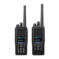
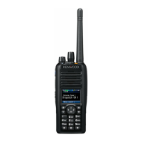
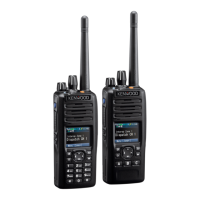
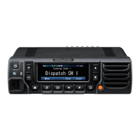
Kenwood NX-5200 F3 Specifications

General IconGeneral
Frequency Range136-174 MHz
Number of Channels1024
Waterproof RatingIP67
Operating Temperature-30°C to +60°C
Digital ModeNXDN, DMR
Analog ModeFM
Channel Spacing25 kHz
Power Output5W
RF Output Power5W
Digital ProtocolNXDN
Modulation16K0F3E
Operating Voltage7.5 V DC

Related product manuals