Do you have a question about the Kenwood NX-5700HB and is the answer not in the manual?
Guides the initial setup and configuration of the transceiver system.
General physical and operational characteristics of the transceiver.
Receiver performance metrics like sensitivity and selectivity.
Transmitter performance metrics like power output and emission.
Explains transceiver modes and how to enter them.
Details panel test and tuning modes for checks and adjustments.
Guides PC connection, cable description, and software usage for programming.
Explains firmware upgrading, connection, and programming steps.
Details transceiver data cloning procedures and password input.
Guides on accessing and writing data via front panel programming.
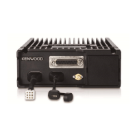
Provides a visual overview of the main unit's external features and dimensions.
Details configuration of control heads and DIP switch settings for operation.
Describes the ignition function for controlling radio power with a car key.
Guides connection of the ignition sense cable to radio and control head.
Guides connecting the external speaker to radio and control head.
Explains the installation procedure for the horn alert function.
Lists module accessories and provides installation instructions.
Details reconfiguring D-SUB 25-pin connector settings (AUXIO9 to CTS, DI to RTS).
General transceiver overview and frequency settings explanation.
Details RF, IF, and Audio Amplifier circuits for signal reception.
Explains audio, baseband, drive, final amplifiers, and APC circuits.
Details TCXO, VCO, and PLL IC functions for frequency synthesis.
Explains MPU, memory circuit, and interface circuit functions.
Describes the Digital Signal Processor (DSP) and its processing capabilities.
Details the power supply circuit and voltage regulation.
Explains encoding and decoding of signaling data (QT, DQT, DTMF, etc.).
Details circuit operation, frequency, and signal paths for Bluetooth and GPS.
Lists and describes components within the main unit (ICs, Transistors, etc.).
Lists and describes components within the BT/GPS module unit.
Lists and describes components within the interface unit.
Details the terminal functions for the main unit's connectors (CN5, CN6, CN7, CN8).
Lists terminal functions for the BT/GPS module unit connectors (CN1, CN9, CN10, J700).
Details terminal functions for the interface unit connectors (25-pin, 9-pin).
Lists important precautions before starting the disassembly process.
Details removing the main unit, antenna, flat spring, and fixed parts.
Steps for removing the molding cover, which is tape-fixed.
Provides guidelines for proper wire routing during reassembly.
Guides on correctly attaching the rubber seal to the chassis.
Notes on replacing sheets and cushions during reassembly.
Explains the transceiver controls and preparation for tuning.
Outlines panel test mode features and key operations.
Details the key operations within the panel test mode.
Lists test frequencies and signaling parameters for adjustment.
Details signaling test configurations for various modes (Analog, P25, NXDN).
Steps to enter the transceiver tuning mode.
Explains key operations within the panel tuning mode.
Details frequency adjustments using 5 or 9 reference levels.
Adjustments for receiver sensitivity, RSSI, and squelch levels.
Adjustments for various transmit power levels (High, Medium, Low).
Adjustments for signal deviation in various modes (QT, DQT, LTR, DTMF, MSK, CWID).
Adjusts transceiver frequency and transmitter ramp settings.
Adjusts VCO lock voltage for receiver and transmitter.
Verifies frequency accuracy and power output levels.
Tests microphone sensitivity and deviation.
Checks medium and low power output levels.
Checks receiver sensitivity using SSG.
Sets DC voltage, SSG modulation, and adjusts VCO lock voltage.
Fine-tunes transmit power levels (High, Medium, Low).
Adjusts signal deviation for various modes (Balance, P25, NXDN, etc.).
Sets AF level and adjusts receiver sensitivity levels.
Adjusts RSSI reference, low/high RSSI, and squelch levels.
Diagnoses faults related to BGA ICs (MPU/DSP, DDR, Flash Memory).
Flowchart for troubleshooting GPS function failures.
Flowchart for troubleshooting Bluetooth function failures.
Information on main unit part numbers and how to identify units.
Details on service unit accessories, data, and post-PCB replacement steps.
Illustrates the layout of the ESN label for identification.
Shows the component layout of the interface unit printed circuit board.
Shows the component layout of the module unit printed circuit board.
Shows the component layout of the main unit printed circuit board.
Exploded view showing assembly and part references.
List of electrical components and their part numbers.
List of packing materials and accessories for the transceiver.
Lists parts for the main unit, including screws and connectors.
Lists parts for the Bluetooth/GPS module unit.
Lists parts for the interface unit.
| Frequency Range | 136-174 MHz |
|---|---|
| Operating Voltage | 13.6 V DC ±15% |
| Operating Temperature | -30°C to +60°C |
| IP Rating | IP54 |
| Channel Capacity | 1024 |
| Modulation | FM |
| Dimensions | 144 x 45 x 160 mm |
| Battery Life | N/A (Mobile Transceiver, typically vehicle-mounted) |
| Channel Spacing | 6.25/12.5/25 kHz |