6
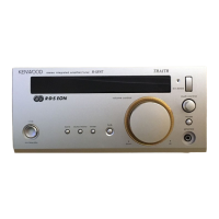
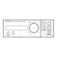
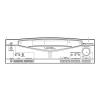
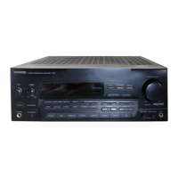
R-SE9/SE9T
CIRCUIT DESCRIPTION
✣ E/T type only, other types unused.
The RDS PTY AF search always corresponds to a span search of 100kHz. Therefore, a span search of 50 KHz
cannot be performed.
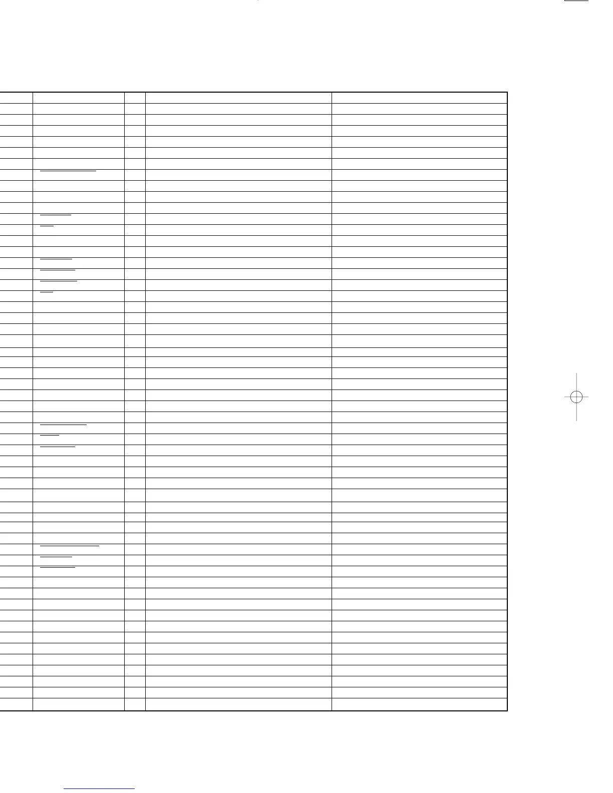
Pin No. Name I/O Description Active
1~7 7G~1G O FL grid 7~1 —
8 VDD — Micro processor power supply (+5V) —
9 E2PROM SCL O E2PROM control clock —
10 E2PROM SDA I/O E2PROM control data —
11 ENC C — Multi control encoder input A —
12 ENC D — Multi control encoder input B —
13 A CLASS ON O Power ON/OFF control signal H : OFF L : ON
14 SEL STB O Selector IC strobe —
15 SEL/PLL CLK O SEL/PLL IC control clock —
16 SEL/PLL DATA O SEL/PLL IC control data —
17 RESET I Microprocessor reset L : RESET ON
18 CE I AC OFF(MAIN POWER) detection Signal L : AC OFF
19 PLL DO O IF count data —
20 AVSS — A/D power SUPPLY (GND) —
21 PLL CE O PLL chip enable control L : CE
22 T MUTE O Tuner mute signal L : MUTE ON
23 STEREO I Stereo signal detection L : STEREO ON
24 SD I Synchronized signal detection —
25 VOL SCL O Electric volume IC control clock —
26 VOL SDA O Electric volume IC control data —
27 LEVEL IN I Volume level input —
✣ 28 S.LEVEL(RDS) I Signal level —
29 A VDD — A/D power supply (+5V) —
30 A VREF — A/D reference voltage(+5V) —
31, 32 OSC — 32kHz oscillator —
33 Vss — Microprocessor power supply (GND) —
34, 35 OSC — 4.19MHz oscillator —
36 S.DATA I/O 16bit system data —
37 S.BUSY I/O 16 bit system busy H : BUSY L : READY
38 H.P. MUTE O Head phones mute signal L : ON
39 ATT O -6dB attenuator H : OFF L : ON
40 A MUTE O Audio mute signal L : ON
41 HIGH RELAY O AMP high relay control H : ON L : OFF
42 LOW RELAY O AMP low relay control H : ON L : OFF
43 SP RELAY O Speaker relay control H : ON L : OFF
✣ 44 CLK(RDS) I RDS clock —
✣ 45 DATA(RDS) I RDS data —
46 PROTECTION I Protection detection H : ON L : OFF
47 REMOCON I Remote control input —
48 IC — — —
49 EX. BASS LED O EX. BASS LED H : OFF L : ON
50 FAN HI O Fan speed control signal H : LOW L : HIGH
51 FAN ON O Fan power supply control signal H : OFF L : ON
52 VDD — Microprocessor power supply (+5V) —
53 ENCA I Volume encoder in put A —
54 ENC B I Volume encoder input B —
55 HEAD PHONE I Head phones signal detection H : ON L : OFF
56, 57 NC O — —
58~60 KR2~KR0 I KEY return 2~0 H : KEY ON
61~64 SEG16~13/KS3~0 O FL Segment 6~13 /key scan 3~0 H : ON
65~70 SEG12~SEG7 O FL Segment 12~7 H : ON
71 V load — FL drive power supply (-30V) —
72~77 P6 SEG6~SEG1 O FL Segment 6~1 H : ON
78 NC O — —
79, 80 9G, 8G O FL grid 9, 8 —
3-2 Pin description
R-SE9/SE9T(K) 1P 98.4.25 14:46 y[W 13
 Loading...