Do you have a question about the Kenwood SP-100 and is the answer not in the manual?
Details the R-1000 receiver's signal path, components, and antenna inputs.
Explains the Phase Locked Loop circuit's configuration, oscillators, and mixers.
Explains the circuits for counting, clock functions, and timer operations.
Details the MSM5524 integrated circuit's functions, pins, and electrical characteristics.
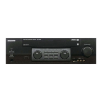
Illustrates and labels the front panel controls, knobs, and indicators.
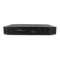
Illustrates and labels the rear panel connectors, jacks, and ports.
Shows the internal components and PCB layout from the top perspective.
Shows the internal components and PCB layout from the bottom perspective.
Provides the circuit diagram and component layout for the PLL unit.
Provides the circuit diagram and component layout for the RX unit.
Provides the circuit diagram and component layout for the VFO unit.
Details resistor types, values, wattage, and tolerance codes.
Details capacitor types, values, tolerances, and temperature coefficients.
Lists general parts such as cases, panels, and accessories.
Lists miscellaneous components, hardware, and accessories.
Lists parts specific to the PLL unit assembly.
Lists semiconductor components including transistors and ICs.
Lists semiconductor components including transistors and ICs.
Lists coils and crystals used within the receiver circuitry.
Lists potentiometers, resistors, and trimmer components.
Lists various types of capacitor components.
Lists parts specific to the VFO assembly unit.
Lists parts specific to the VFO unit.
Lists parts specific to the RX unit.
Lists semiconductor components including transistors and ICs.
Lists switches and relays used in the unit.
Lists potentiometer components.
Lists resistor components.
Lists trimmer components.
Lists capacitor components.
Lists capacitor components.
Illustrates the disassembly steps for the unit's case.
Illustrates the disassembly steps for the front panel and RX unit.
Illustrates the disassembly steps for the rear panel and chassis.
Lists necessary test equipment for performing adjustments.
Outlines pre-adjustment steps and initial control settings.
Instructions for adjusting the unit's power supply voltage.
Procedure for adjusting the RB line voltage.
Details the adjustment of the Beat Frequency Oscillator.
Procedure to check the VFO output level.
Steps for adjusting the VCO voltage.
Procedure for adjusting the clock oscillator frequency.
Adjustments for the RF and IF amplifier stages.
Procedure for adjusting the IF trap coil.
Instructions for adjusting MCF using a tracking generator.
Instructions for adjusting MCF using a Signal Generator.
Procedure for adjusting the noise blanker circuit.
Steps for calibrating the S-meter.
Procedure for adjusting the 10 MHz crystal frequency.
Procedure for adjusting the 42.555 MHz Band Pass Filter.
Procedure for adjusting the 6 to 35 MHz Band Pass Filters.
Alignment procedures for the RX unit with diagrams.
Alignment procedures for the PLL unit with diagrams.
Alignment procedures for the VFO unit with diagrams.