Do you have a question about the Kenwood TH-79 A and is the answer not in the manual?
| Brand | Kenwood |
|---|---|
| Model | TH-79 A |
| Category | Transmitter |
| Language | English |
Steps for removing the main circuit board from the device.
Instructions for detaching the holder component.
Steps to detach the 'A' unit from the main case.
Guide to removing the shield cover and 'B' unit.
Procedure for detaching the LCD assembly.
Explains the radio's frequency configuration and IF channels.
Details the signal path for receiving radio signals.
Describes the UHF reception signal path and intermediate frequencies.
Describes the VHF reception signal path and intermediate frequencies.
Explains the sub-VHF reception signal path.
Explains the sub-UHF reception signal path.
Details how audio signals are processed and output.
Outlines the signal path for transmitting radio signals.
Explains the audio modulation process for transmission.
Describes the amplification stages in the transmission path.
Explains the Automatic Power Control circuit.
Describes the circuit that protects against overheating.
Details the Phase-Locked Loop circuit for frequency synthesis.
Explains the 12.8MHz quartz crystal oscillator circuit.
Describes the phase comparison process in the PLL.
Explains the lock voltage generation for VCO regulation.
Details the VHF Voltage-Controlled Oscillator circuit.
Details the UHF Voltage-Controlled Oscillator circuit.
Describes the circuit that detects PLL unlocking.
Outlines the radio's power supply system.
Explains the Ni-Cd battery charging circuit.
Details the power supply switching and distribution.
Describes the microprocessor and its related circuits.
Explains the circuit for maintaining settings during power loss.
Details the circuit for monitoring battery voltage.
Describes the circuit that reduces power consumption.
Explains the circuits controlling the LEDs.
Details the input circuit for the rotary encoder and keys.
Describes auxiliary circuits like CTCSS and DTMF.
Explains the Continuous Tone-Coded Squelch system.
Explains the Digital Tone Squelch System.
Describes timing for DTMF decode.
FM/AM IC (VHF) function and description.
FM IC (UHF) function and description.
Shift register function and description.
PLL IC function and description.
Doubler circuit function and description.
Doubler circuit function and description.
Temperature protection circuit function and description.
RF amplifier function and description.
Constant voltage circuit function and description.
Backflow prevention function and description.
Noise rectification (VHF squelch circuit).
Noise rectification (UHF squelch circuit).
Pin connections and functions for the microcomputer.
Detailed pinout and function for the microcomputer.
Pin numbering, port names, I/O, and pull-up details.
Pin connection diagram and descriptions for shift registers.
Pin connection diagram and descriptions for DTMF decoder.
Pin connection for the DC-DC converter.
Pin assignment for the power module.
List of parts for the TH-79 A/E model.
Continuation of parts list for TH-79 A/E.
Parts list for the CTCSS Unit (TSU-8).
Parts list for the TX-RX unit.
Continuation of TX-RX unit parts list.
Continuation of TX-RX unit parts list.
Continuation of TX-RX unit parts list.
Exploded view diagram of parts assembly (Section A).
Exploded view diagram of parts assembly (Section B).
Continued exploded view of parts assembly (Section B).
Packing details for X and M4 models.
Packing details for models except X and M4.
Lists the necessary test equipment for adjustments.
Details the service jig used for adjustments.
Initial steps and settings before performing adjustments.
Guide to operating the "Set Mode" for configuration.
Step-by-step instructions for entering and using "Set Mode".
General settings applicable to all adjustments.
Adjustment procedures for the VHF receiver section.
Adjustment procedures for the sub-UHF receiver section.
Adjustment procedures for the UHF receiver section.
Adjustment procedures for the UHF transmitter section.
Adjustment procedures for the VHF transmitter section.
Adjustments for other sections like LCD contrast.
Diagram showing the layout of adjustment points.
Pin functions for CN1, CN302 connectors.
Pin functions for CN303 connector.
Pin functions for CN306, CN307 connectors.
Wiring diagram for IC100 (UHF Power Module).
Wiring diagram for IC101 (VHF Power Module).
Schematic for the CTCSS Unit (TSU-8).
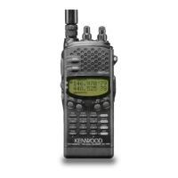
General specifications like frequency range, mode, and dimensions.
Transmitter specifications including output power and current.
Receiver specifications including sensitivity and selectivity.