EasyManua.ls Logo

Kenwood TH-K2AT Service Manual

Kenwood TH-K2AT
63 pages
To Next Page IconTo Next Page
Page #1 background imageLoading...
Page #1 background image
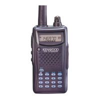
144MHz FM TRANSCEIVER
TH-K2AT/K2E/K2ET
© 2003-8 PRINTED IN JAPAN
B51-8658-00 (S) 836
SERVICE MANUAL
DISASSEMBLY FOR REPAIR ................................... 2
CIRCUIT DESCRIPTION ............................................ 6
SEMICONDUCTOR DATA ...................................... 14
COMPONENTS DESCRIPTION .............................. 15
PARTS LIST ............................................................. 17
EXPLODED VIEW .................................................... 23
PACKING ................................................................. 25
ADJUSTMENT ........................................................ 27
TERMINAL FUNCTION ........................................... 43
PC BOARD
TX-RX UNIT (X57-674X-XX) (A/ 3) ................... 44
TX-RX UNIT (X57-674X-XX) (B/ 3),(C/ 3) .......... 48
CONTENTS
SCHEMATIC DIAGRAM .......................................... 50
LEVEL DIAGRAM .................................................... 55
BLOCK DIAGRAM ................................................... 56
BC-21 (WALL CHARGER) ....................................... 58
PB-43N (Ni-M H BATTERY PACK) .......................... 58
BT-14 (BATTERY CASE) ......................................... 59
PG-4Y (PROGRAMMING INTERFACE CABLE) ..... 59
MCP-1A (MEMORY CONTROL PROGRAM) ......... 59
SPECIFICATIONS ................................. BACK COVER
Knob (ENC)
(K29-5159-03)
Knob (VOL)
(K29-5150-03)
Cabinet assy
(16key)
(A02-3819-23)
Helical Antenna
(T90-1018-25)
Key top (16key)
(K29-9272-02)
Front glass
(B10-2746-03)
Knob
(PTT/LAMP/MON)
(K29-9274-03)
Knob (ENC)
(K29-5159-03)
Knob (VOL)
(K29-5150-03)
Cabinet assy
(4key)
(A02-3818-23)
Helical Antenna
(T90-1018-25)
Key top (4key)
(K29-9276-02)
Front glass
(B10-2746-03)
Knob
(PTT/LAMP/MON)
(K29-9274-03)
TH-K2AT/ K2ET TH-K2E
Cap
(SP/MIC/DC IN)
(B09-0675-03)
Cap
(SP/MIC/DC IN)
(B09-0675-03)

Other manuals for Kenwood TH-K2AT

Question and Answer IconNeed help?

Do you have a question about the Kenwood TH-K2AT and is the answer not in the manual?

Kenwood TH-K2AT Specifications

General IconGeneral
BrandKenwood
ModelTH-K2AT
CategoryTransceiver
LanguageEnglish

Summary

DISASSEMBLY FOR REPAIR

How to remove the case assembly from the chassis

Step-by-step guide to detach the radio's external case from its main chassis.

How to remove the PC board

Detailed steps for safely removing various printed circuit boards from the unit.

CIRCUIT DESCRIPTION

Frequency Configuration

Details the frequency ranges and configuration for transmission and reception.

Receiver System

Explains the signal path and components within the radio's receiver section.

Transmitter System

Describes the signal flow and components within the radio's transmitter section.

SEMICONDUCTOR DATA

MPU Pin Function

Lists the functions and I/O for each pin of the MPU (IC8).

COMPONENTS DESCRIPTION

TX-RX UNIT Components

Details the use, function, and compatibility of components on the TX-RX unit.

PARTS LIST

TX-RX UNIT Parts

Comprehensive list of parts used in the TX-RX unit, including part numbers and descriptions.

EXPLODED VIEW

Exploded View (TH-K2AT / K2ET)

Diagram showing the physical arrangement of components for disassembly and assembly.

PACKING

Packing (K, M, E and E3 types)

Illustrates the items included in the packaging for different model types.

ADJUSTMENT

Single Tone Mode

Mode for checking DTMF deviation using single tone frequencies.

Adjustment Mode Overview

Procedure to enter Adjustment Mode and general operation guidelines.

Receiver Section Adjustments

Procedures for adjusting receiver parameters like BPF, IF response, and Squelch.

Transmitter Section Adjustments

Procedures for adjusting transmitter parameters like TX power and modulation.

TERMINAL FUNCTION

TX-RX UNIT Terminals

Lists the pin functions and connections for various connectors on the TX-RX unit.

PC BOARD

TX-RX UNIT (A/3) Component Side View

Shows the component layout on the component side of the TX-RX unit (A/3).

TX-RX UNIT (A/3) Foil Side View

Shows the component layout on the foil side of the TX-RX unit (A/3).

SCHEMATIC DIAGRAM

TX-RX UNIT (X57-674X-XX)(A/3) Schematic

Detailed schematic diagram of the TX-RX unit (A/3) showing circuit connections.

LEVEL DIAGRAM

Transmitter and Receiver Levels

Illustrates signal levels at various points in the transmitter and receiver sections.

BLOCK DIAGRAM

Radio System Block Diagram

Shows the functional blocks and interconnections within the radio's system.

BC-21 (WALL CHARGER) / PB-43N (Ni-MH BATTERY PACK)

BC-21 Specifications

Provides specifications for the BC-21 wall charger.

PB-43N Specifications

Details specifications and schematic for the PB-43N battery pack.

BT-14 (BATTERY CASE) / PG-4Y (PROGRAMMING INTERFACE CABLE) / MCP-1A (MEMORY CONTROL PROGRAM)

MCP-1A (Memory Control Program)

Information on obtaining and using the MCP-1A memory control software.

SPECIFICATIONS

General Specifications

Lists general technical specifications for the transceiver model.

Related product manuals