EasyManua.ls Logo

Kenwood TK-2202 User Manual

Kenwood TK-2202
43 pages
To Next Page IconTo Next Page
Page #1 background imageLoading...
Page #1 background image
VHF FM TRANSCEIVER
TK-2202/2206
© 2004-2 PRINTED IN JAPAN
B51-8677-00 (S) 1246
SERVICE MANUAL
GENERAL .............................................................2
SYSTEM SET-UP .................................................2
REALIGNMENT....................................................3
DISASSEMBLY FOR REPAIR ..............................5
CIRCUIT DESCRIPTION .......................................8
TERMINAL FUNCTION......................................12
SEMICONDUCTOR DATA .................................12
COMPONENTS DESCRIPTION .........................13
PARTS LIST........................................................14
EXPLODED VIEW...............................................20
PACKING ............................................................21
ADJUSTMENT ...................................................23
PC BOARD
TX-RX UNIT (X57-6870-20)..........................28
SCHEMATIC DIAGRAM.....................................32
BLOCK DIAGRAM..............................................36
LEVEL DIAGRAM...............................................38
KSC-31 / KNB-29N / KNB-30A / KBH-10 .........39
SPECIFICATIONS............................BACK COVER
CONTENTS
Antenna
(T90-1036-05): TK-2202(K,M)
(KRA-26: Option) TK-2206 (M)
Knob (VOLUME)
(K29-9309-03)
Knob (PTT)
(K29-9308-03)
Cabinet assy
(A02-3852-23)(8CH):
TK-2202(K,M)
(A02-3851-23)(16CH):
TK-2206(M)
Knob (CH-SELECTOR)
(K29-9318-03)
TK-2206 :
Does not come with antenna.
Antenna is available as an option.
Photo is TK-2202.
Question and Answer IconNeed help?

Do you have a question about the Kenwood TK-2202 and is the answer not in the manual?

Kenwood TK-2202 Specifications

General IconGeneral
Frequency Range136-174 MHz
Channel Capacity16
Power Output5W
Channel Spacing12.5/25 kHz
Operating Voltage7.5V
Ingress ProtectionIP54
ModulationFM
Voltage7.5V
TypePortable
MIL-STDMIL-STD-810

Summary

General and System Set-up

Personal Safety Precautions

Recommended precautions for safe operation and servicing.

Disassembly for Repair

Case and Battery Lever Removal

Steps to detach the radio's casing and battery lever.

TX-RX Unit Removal

Procedure for detaching the transmitter/receiver board.

Parts List

TK-2202/2206 Model Parts

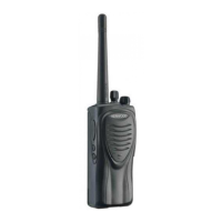
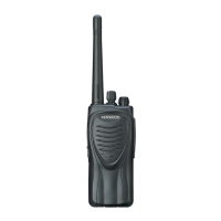
List of parts for TK-2202/2206 models.

TX-RX Unit Component List

Detailed list of components for the TX-RX unit.

Adjustment Procedures

Transmitter Section Adjustments

Procedures for adjusting transmitter parameters.

Receiver Section Adjustments

Procedures for adjusting receiver parameters.

PC Board Layouts

Schematic Diagram

TX-RX Unit Circuit Diagram

Detailed circuit diagram for the TX-RX unit.

Block Diagram

Transceiver Functional Block Diagram

High-level functional blocks of the transceiver.

Specifications

General Specifications

Overall operating parameters of the transceiver.

Receiver Specifications

Performance metrics for the receiver section.

Transmitter Specifications

Performance metrics for the transmitter section.

Related product manuals