EasyManua.ls Logo

Kenwood TK-2317 M3 User Manual

Kenwood TK-2317 M3
52 pages
To Next Page IconTo Next Page
Page #1 background imageLoading...
Page #1 background image
SERVICE MANUAL
This product complies with the
RoHS
directive for the European market
.
This product uses Lead Free solder
.
© 2011-4 PRINTED IN JA PAN
B51-8972-00
(
Y
)
PDF
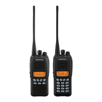
VHF FM TRANSCEIVER
TK-2317
CONTENTS
GENERAL ....................................................2
SYSTEM SET-UP .........................................3
REALIGNMENT ...........................................3
DISASSEMBLY FOR REPAIR .....................9
CIRCUIT DESCRIPTION ...........................12
SEMICONDUCTOR DATA .........................17
COMPONENTS DESCRIPTION ................18
PARTS LIST ...............................................19
EXPLODED VIEW ......................................27
PACKING ...................................................28
ADJUSTMENT ...........................................29
PC BOARD
TX-RX UNIT (X57-7880-21) ....................34
SCHEMATIC DIAGRAM ............................38
BLOCK DIAGRAM .....................................44
LEVEL DIAGRAM ......................................46
OPTIONAL ACCESSORIES
KNB-29N (Ni-MH Battery Pack) ............47
KNB-45L (Li-ion Battery Pack) .............47
KNB-53N (Ni-MH Battery Pack) ............47
KMC-48GPS (GPS Speaker Microphone)
..47
SPECIFICATIONS ..................BACK COVER
Helical antenna
(T90-1050-05)
Button knob
(SIDE1/SIDE2)
(K29-9426-03)
Knob (Selector)
(K29-9427-03)
Knob (Volume)
(K29-9309-13)
Plastic cabinet assy
(A02-4095-23)
Button knob (PTT)
(K29-9425-03)
Key top (7key)
(K29-9463-12)
M3 version
Question and Answer IconNeed help?

Do you have a question about the Kenwood TK-2317 M3 and is the answer not in the manual?

Kenwood TK-2317 M3 Specifications

General IconGeneral
Power Output5W
Operating Voltage7.5 V DC ± 20%
IP RatingIP54
Modulation16K0F3E / 11K0F3E
Operating Temperature-30°C to +60°C
Frequency Range136-174 MHz
Channel Capacity128
Battery Life12 hours
Channel Spacing12.5 / 25 kHz
MIL-STDMIL-STD 810 C/D/E/F/G

Summary

GENERAL

PERSONAL SAFETY

Lists precautions for safe operation.

SYSTEM SET-UP

Initial Setup Procedure

Outlines the steps for setting up the transceiver.

REALIGNMENT

Operational Modes

Describes different operational modes.

PC Mode Setup

Details PC programming requirements and connections.

Wireless Clone Mode

Explains and details wireless cloning functionality.

Self Programming Mode

Details the self-programming mode.

Firmware Version Information Mode

How to view firmware version.

DISASSEMBLY FOR REPAIR

Removing Case Assembly

Steps to remove the case.

Removing TX-RX Unit

Steps to remove the TX-RX unit.

Attaching Battery Release Lever

Steps to attach the lever.

Mounting Chassis to Case

Steps to mount the chassis.

TX-RX Unit Mounting Sequence

Screw order for TX-RX unit.

CIRCUIT DESCRIPTION

Frequency Configuration

Explains frequency setup.

Receiver System Overview

Describes the receiver block diagram.

IF Amplifier Circuit

Details the IF amplifier stages.

Drive and Final Amplifier Circuit

Explains drive and final amplifier stages.

Control Circuit Overview

Describes the control circuit.

Signaling Circuit - Encode

Explains encode signals (QT, DQT, 2-tone, MSK/DTMF).

SEMICONDUCTOR DATA

MCU Pin Assignments

Lists MCU pin functions and assignments.

COMPONENTS DESCRIPTION

TX-RX Unit Components

Lists and describes components in the TX-RX unit.

PARTS LIST

Capacitors and Resistors

Details types, values, and coding.

EXPLODED VIEW

Radio Assembly Diagram

Shows exploded view of radio components.

PACKING

Packing Contents Diagram

Illustrates the items included in the package.

ADJUSTMENT

Test Equipment

Lists required equipment for alignment.

Frequency and Signaling Settings

Lists frequencies and signaling types for adjustment.

Common Section Adjustments

Details adjustments for common parameters.

Transmitter Section Adjustments

Details transmitter tuning parameters.

Transmitter Deviation Adjustments

Details deviation tuning for specific modes.

Receiver Section Adjustments

Details receiver tuning parameters.

Receiver Squelch and RSSI Adjustments

Details tuning for squelch and RSSI.

PC BOARD

Component Side View (TX-RX UNIT)

Shows component placement on the PC board.

Foil Side View (TX-RX UNIT)

Shows component placement on the foil side of the PC board.

SCHEMATIC DIAGRAM

Overall Schematic

Presents the complete circuit schematic.

BLOCK DIAGRAM

System Block Diagram

Illustrates the functional blocks of the transceiver.

LEVEL DIAGRAM

Signal Level Diagrams

Shows signal levels in receiver and transmitter sections.

OPTIONAL ACCESSORIES

Battery Packs and Microphone

Lists and describes available accessories.

SPECIFICATIONS

Technical Specifications

Lists detailed technical parameters of the transceiver.

Related product manuals