Do you have a question about the Kenwood TK-5710 and is the answer not in the manual?
Outlines the intended audience and scope of the service manual.
Provides instructions for ordering replacement parts, emphasizing the need for part numbers.
Lists recommended safety precautions for handling the equipment and during operation.
Covers unpacking, licensing requirements, pre-installation checks, and planning.
Guidance on planning radio antenna and accessory mounting and cable runs.
Discusses mounting the radio using a universal bracket and DC power connection.
Planning antenna systems and radio locations for control stations.
Refers to manual sections for servicing and specifies required software version.
Introduces the transceiver main unit and options for system configuration.
Flowchart to select transceiver setup based on options like remote kits.
Lists part numbers for service manuals of KRK-5/6DH and KCH-14/15.
Lists various operational modes available on the transceiver.
Details the key combinations required to enter different operational modes.
Refers to ADJUSTMENT section for setting methods for Panel Test and Tuning Modes.
Explains programming via PC using interface cable and software.
Describes KPG-43 cable and KPG-95D software for PC programming.
Details on modifying the KPG-43 cable for PC tuning adjustments.
Procedure for upgrading transceiver firmware via PC.
Procedure for transferring programming data between transceivers via microphone jacks.
Instructions for writing frequency and signaling data directly using the transceiver.
Steps to enter self-programming mode, including password entry if applicable.
Procedure for writing new data into memory using the self-programming mode.
Details key operations for self-programming mode.
Explains how to use the MIC keypad for inputting data.
Describes the normal mode operation and key functions.
Visual flowchart illustrating the self-programming mode sequence.
Procedure to view firmware version information using PF3 key.
Flowchart for adjusting the transceiver's internal clock settings.
Instructions for installing the KCH-14/15 front panel kit to the transceiver.
Information on the KRK-5 remote kit for operating the transceiver remotely.
Steps for connecting the KRK-5 rear panel to the front panel kit.
Instructions for connecting the KCT-22 control cable.
Steps for installing the display unit with an angle bracket.
Information on the KRK-6DH kit for connecting two displays to the transceiver.
Details the optional KCT-18 cable for ignition function and timed power-off.
Instructions for installing the VGS-1 unit into the transceiver.
Describes connecting the voice scrambler board via connector or lead wire.
Instructions for connecting the ANI board to the control unit's component side.
Information on connecting external speakers KES-5/6 to the transceiver.
Instructions for connecting external speakers to the remote kit's 12-pin connector.
Instructions for modifying the KCH-14 display unit to increase audio output.
Instructions for using the transceiver as a public address speaker.
Details on enabling the horn alert function by modifying the control unit.
Step-by-step procedure for disassembling the TK-5710(B) model.
Step-by-step procedure for disassembling the TK-5710H(B) model.
Disassembly procedures applicable to both models.
Guidelines for reassembling the unit, focusing on affixing sheets.
Instructions for applying lubricant to case packing grooves for waterproofing.
Instructions for affixing sheets and aligning cables during assembly.
Confirms proper fitting of case packing to the chassis after installation.
Provides the correct order for tightening screws when reassembling the upper/lower case.
Describes the transceiver as a VHF/FM/APCO portable unit.
Explains the receiver's superheterodyne system and transmitter frequency generation.
Details the receiver's front-end RF amplifier and first local oscillator stages.
Describes the 1st IF signal path through MCFs and IF amplifier.
Explains mixing of 1st IF signal with 2nd local signal.
Details the 2nd IF signal path through ceramic filters.
Explains the AF signal path through filters, switches, and amplifiers.
Describes how the squelch voltage is generated and compared.
Outlines the components of the transmitter system.
Describes transmit signal amplification through drive amplifiers.
Explains the final amplifier circuit for TK-5710(B).
Explains the final amplifier circuit for TK-5710H(B).
Circuit reducing APC voltage based on power module temperature.
Circuit reducing APC voltage based on module temperature.
Lists the components of the PLL frequency synthesizer.
Explains the VCXO's role in generating reference frequency and its adjustment.
Describes the RX and TX VCOs and their functions.
Explains the rheostat IC's function in controlling VCO oscillation frequency.
Describes the PLL IC's function in phase comparison and frequency lock.
Explains how diode switches change signal output paths.
Details the control circuit's components and functions.
Describes memory circuits consisting of CPU, flash memory, and EEPROM.
Explains the circuit that detects temperature to correct squelch characteristics.
Details the DSP circuit's processes, including encoding and decoding.
Explains the FPGA's functions, including demodulation and level conversion.
Describes the power supply circuit, including voltage regulation and protection.
Explains how signaling data is generated, superposed, and routed.
Explains the compander function for noise reduction via compressor and expander.
Pin assignments, port names, I/O, and functions for the CPU.
Pin assignments and functions for shift register ICs.
Pin assignments and functions for the D/A converter IC.
Lists components (ICs, transistors, diodes) and their descriptions for the control unit.
Lists components for the TX-RX unit and their descriptions.
Lists components for the final units (TK-5710(B) and TK-5710H(B)).
Details capacitor types, shapes, coefficients, voltage, values, and tolerances.
Provides dimension codes, values, and tolerances for chip capacitors.
Details resistor types, shapes, ratings, coefficients, values, and tolerances.
Table mapping dimension codes to L, W, and T values for chip resistors.
Lists rating wattage codes for chip resistors and their corresponding wattage.
Lists part numbers, descriptions, and destinations for TK-5710(B) components.
Lists part numbers, descriptions, and destinations for TK-5710H(B) components.
Lists part numbers and descriptions for TK-5710(B) final unit components.
Continues listing part numbers and descriptions for TK-5710(B) final unit components.
Lists part numbers and descriptions for TK-5710H(B) final unit components.
Continues listing part numbers and descriptions for TK-5710H(B) final unit components.
Lists part numbers and descriptions for control unit components.
Continues listing part numbers and descriptions for control unit components.
Continues listing part numbers and descriptions for control unit components.
Continues listing part numbers and descriptions for control unit components.
Lists part numbers and descriptions for TX-RX unit components.
Lists part numbers and descriptions for control unit components.
Continues listing part numbers and descriptions for TX-RX unit components.
Continues listing part numbers and descriptions for TX-RX unit components.
Continues listing part numbers and descriptions for TX-RX unit components.
Continues listing part numbers and descriptions for TX-RX unit components.
Continues listing part numbers and descriptions for TX-RX unit components.
Shows exploded view of TX-RX unit, display units, and control unit.
Identifies different types of screws (A, B, D, E, H, I, J) used in the assembly.
Shows exploded view of TX-RX unit, display units, and control unit for TK-5710H(B).
Identifies different types of screws (A, B, C, E, F, G, H, I, J) used in the assembly.
Shows the placement of the inner carton case and its contents.
Illustrates how the protection bag is used for the transceiver.
Shows the placement of packing fixtures for securing the transceiver.
Depicts the item carton case and its contents.
Shows the placement of the inner carton case and its contents for TK-5710H(B).
Illustrates the use of the protection bag for the TK-5710H(B).
Shows the placement of packing fixtures for securing the TK-5710H(B).
Depicts the item carton case and its contents for TK-5710H(B).
Illustrates the control layout for KCH-14 and KCH-15 panel types.
Describes features and operation of the transceiver's test mode.
Explains the function of keys in different operational modes.
Explains the meaning of LEDs and the LCD display in panel test mode.
Lists filter display modes (Wide, Narrow, APCO) and their conditions.
Notes that transceiver is adjusted for frequencies shown.
Table listing channel numbers with their corresponding RX and TX frequencies.
Lists various test signaling types for RX, TX, and APCO modes.
Lists necessary equipment like power supply and dummy load for tuning.
Instructions on how to enter tuning mode and use PF keys for adjustment.
Shows the LCD display during panel tuning mode.
Provides frequency settings for assist voltage and other levels.
Lists adjustment items, their display codes, mode settings, tuning points, and notes.
Flowcharts illustrating the process for various adjustment items.
Steps for measuring Bit Error Rate using a digital radio tester.
Instructions for adjusting deviation for C4FM (APCO).
Diagrams showing adjustment points on the final units and TX-RX unit.
Lists necessary test equipment and their major specifications for alignment.
Warning about isolating the RX AF output's DC component.
Details test cables for microphone input, speaker output, and filter adjustments.
Details the setting process, assist voltage, and BPF adjustments.
Instructions for adjusting MCF coils for wide and narrow band waveforms.
Instructions for adjusting the 2nd local frequency.
Procedure for adjusting quadrature coils using SSG output.
Steps for adjusting RTC oscillation frequency using PC tuning mode.
Details adjustments for frequency, max power, high power, low power, and DQT balance.
Procedure for adjusting maximum deviation for FM and APCO modes.
Procedure for adjusting APCO high deviation.
Procedure for checking MIC sensitivity in panel test mode.
Procedure for adjusting QT deviation for wide and narrow bands.
Procedure for adjusting DQT deviation for wide and narrow bands.
Procedure for adjusting DTMF deviation for wide and narrow bands.
Procedure for adjusting MSK deviation for wide and narrow bands.
Procedure for adjusting single tone deviation for wide and narrow bands.
Details the adjustment procedure for the RX Front-end.
Procedure for adjusting RSSI reference levels for wide and narrow bands.
Procedure for adjusting RSSI levels at -120dBm for wide and narrow bands.
Procedure for adjusting RSSI levels at -70dBm for wide and narrow bands.
Procedure for setting AF level using volume knob to obtain 2.0V AF output.
Procedure for checking transceiver sensitivity using SSG and AF VTVM.
Procedure for adjusting squelch threshold in wide and narrow bands.
Procedure for adjusting squelch tightness in wide and narrow bands.
Procedure for checking Bit Error Rate in panel test mode.
Lists pin names, I/O, and descriptions for the TK-5710(B) final unit connectors.
Lists pin names, I/O, and descriptions for the TK-5710H(B) final unit connectors.
Lists pin names, I/O, and descriptions for the control unit connectors.
Details pin assignments for various interface connectors.
Details pin assignments for CN755/solder land connecting to the ANI board.
Details pin assignments for CN771/solder land connecting to the scrambler board.
Lists pin assignments for the TX-RX unit connectors.
Details pin assignments for the accessory 9-pin connector.
Lists pin names, I/O, and descriptions for the accessory 9-pin connector.
Lists pin names, I/O, and descriptions for the 12-pin remote kit connector.
Lists pin names, I/O, and descriptions for the TX-RX unit connectors.
Lists pin names, I/O, and descriptions for the D-SUB 25-pin connector.
Continues listing pin assignments for the accessory 9-pin connector.
Continues listing pin assignments for the 12-pin remote kit connector.
Shows the component layout of the TK-5710(B) final unit's component side.
Shows the component layout of the TK-5710(B) final unit's foil side.
Continues showing component layout of the TK-5710(B) final unit's component side.
Continues showing component layout of the TK-5710(B) final unit's foil side.
Shows the component layout of the TK-5710(B) final unit's component side.
Shows the component layout of the TK-5710(B) final unit's foil side.
Shows the component layout of the TK-5710H(B) final unit's component side.
Continues showing component layout of the TK-5710H(B) final unit's component side.
Continues showing component layout of the TK-5710H(B) final unit's component side.
Shows the component layout of the control unit's component side.
Continues showing component layout of the control unit's component side.
Shows the component layout of the control unit's foil side.
Continues showing component layout of the control unit's foil side.
Shows the component layout of the TX-RX unit's component side.
Continues showing component layout of the TX-RX unit's component side.
Shows the component layout of the TX-RX unit's foil side.
Continues showing component layout of the TX-RX unit's foil side.
Schematic diagram for the TK-5710(B) final unit, showing component connections.
Continues the schematic diagram for the TK-5710(B) final unit.
Schematic diagram for the TK-5710H(B) final unit, showing component connections.
Continues the schematic diagram for the TK-5710H(B) final unit.
Schematic diagram of the control unit, showing component interconnections.
Continues the schematic diagram for the control unit.
Schematic diagram for the TX-RX unit, showing component interconnections.
Shows the power module and APC comparator circuit for the TK-5710(B) final unit.
Continues the schematic diagram for the TK-5710(B) final unit.
Shows the power module and APC circuit for the TK-5710H(B) final unit.
Continues the schematic diagram for the TK-5710H(B) final unit.
Continues the schematic diagram for the TK-5710H(B) final unit.
Continues the schematic diagram for the TK-5710H(B) final unit.
Schematic diagram of the control unit, showing CPU, DSP, and peripheral circuits.
Continues the schematic diagram for the control unit, showing memory, temperature, and power circuits.
Continues the schematic diagram for the control unit, detailing DSP, FPGA, and regulator circuits.
Continues the schematic diagram for the control unit, showing interface connections.
Continues the schematic diagram for the control unit, detailing connector interfaces.
Continues the schematic diagram for the control unit, showing peripheral circuits.
Continues the schematic diagram for the control unit, showing ANI, Scrambler, and display connections.
Continues the schematic diagram for the control unit, detailing peripheral connections.
Block diagram of the final unit, showing major functional blocks and signal flow.
Block diagram of the TX-RX unit, illustrating RF, IF, and DSP stages.
Block diagram of the display unit, showing MIC, CPU, and interface connections.
Block diagram of the control unit, showing CPU, memory, and interface connections.
Block diagram of the ANI board, showing its inputs and outputs.
Block diagram of the scrambler function.
Shows RF input levels for receiver sensitivity measurements.
Shows RF output power levels for transmitter adjustments.
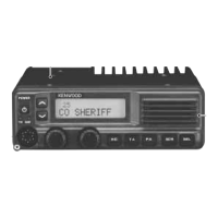
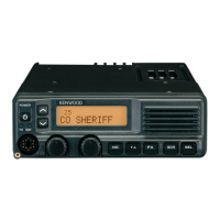
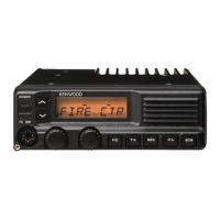
External view of the KCH-14 front panel kit.
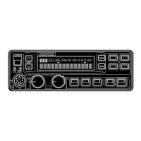
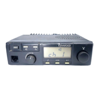
External view of the KCH-15 front panel kit.
External view of the KES-6 external speaker.
Lists general specifications like frequency range, channels, zones, and dimensions.
Details receiver specifications including sensitivity, selectivity, and distortion.
Lists transmitter specifications like RF output power, spurious emissions, and modulation.
Contact information for Kenwood service and support centers worldwide.
| operating voltage | 13.6V DC ± 15% |
|---|---|
| standby current drain | Less than 0.6A |
| transmit current drain | 12A |
| digital sensitivity (5% BER) | 0.25µV |
|---|---|
| analog sensitivity (12dB SINAD) | 0.25µV |
| audio output (Internal KCH-14@3%) | 1.5W/8Ω |
| RF output power | 50W to 5W |
|---|---|
| spurious and harmonics | 80dB |
| microphone impedance | 600Ω |
| dimensions (RF Deck only) | 178 x 60 x 195 mm |
|---|---|
| dimensions with KCH-14 or KCH-15 | 179 x 60 x 231 mm |
| weight (RF Deck only) | 2.4 kg |
| operating voltage | 13.4V DC ± 15% |
|---|---|
| standby current drain | Less than 0.6A |
| transmit current drain | 25A |
| digital sensitivity (5% BER) | 0.25µV |
|---|---|
| analog sensitivity (12dB SINAD) | 0.25µV |
| audio output (Internal KCH-14@3%) | 1.5W/8Ω |
| RF output power | 110W to 50W |
|---|---|
| spurious and harmonics | 80dB |
| microphone impedance | 600Ω |
| dimensions (RF Deck only) | 178 x 60 x 327 mm |
|---|---|
| dimensions with KCH-14 or KCH-15 | 179 x 60 x 363 mm |
| weight (RF Deck only) | 3.9 kg |