Do you have a question about the Kenwood TK-790 and is the answer not in the manual?
Steps and checks before installing the radio, including unpacking, licensing, and initial testing.
Completing the transceiver main unit by adding options. Details configurations.
Safety precautions for transmission, RF connectors, explosive atmospheres, grounding, and qualified technicians.
Guidance on planning the radio's physical placement, antenna, power, and wiring.
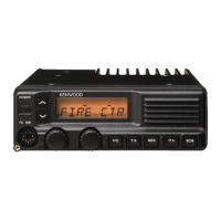
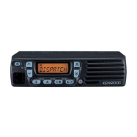
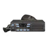
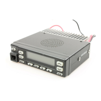
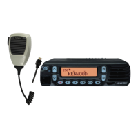
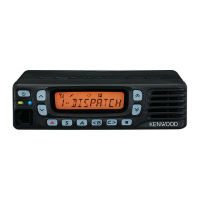
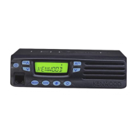
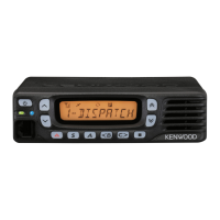
Details the controls and functions of the radio's front panels.
How to use Public Address function to amplify microphone audio through a PA speaker.
How to prevent interference with channels in use.
Details about Emergency Mode Type, Type, DTMF ID, Call Fleet, Call ID.
Explains "All Clone Mode" and "Group Clone Mode".
Explains POWER switch, TX/BUSY indicator, Microphone connector, Volume knob, UP/DOWN knob, and PF1-9 keys.
How to turn on the radio, adjust volume, select group, select channel, and enter carrier squelch mode.
How to open squelch only on receiving a proper 2Tone code.
How DBD code automatically acknowledges and disables transmission.
How to adjust while in PC tuning mode using KPG-43 cable modifications.
How to transmit using Normal ON HOOK Scan Mode and OFF HOOK Scan MODE.
How to open squelch only on receiving a proper DTMF code.
How to use Intercom for communication between control heads.
Details PF Input Ports functions like External HOOK, CH Select, External PTT, Scan, Home Channel, Light Sense, Repeater SW, External Monitor.
Steps for preparing and connecting for PC programming.
How to manually adjust the squelch threshold.
How to change the preset decode QT/DQT and encode QT/DQT.
How to use the radio as a repeater.
How to enter Emergency Mode and transmit an Emergency Call.
Lists topics covered in INSTALLATION: front panel kits, knobs, scrambler, ANI, ignition cable, external speaker, horn alert, terminals, remote kits.
Covers voice scrambler code setting and board connection.
Covers ignition function, timed power off, and necessary modifications.
Covers connecting and installing front panel kits (KCH-10, KCH-11) and accessory knobs.
Increasing horn alert current by installing a relay.
How to connect the ANI board.
Speaker output details for TK-790, KCH-10, KCH-11, and remote kits.
Describes the microphone amplifier, modulation, and final amplifier circuits.
Explains the signal path from antenna to speaker in the receiver circuit.
How the squelch circuit operates and compares voltage levels.
Describes control unit circuits: CPU, memory, shift register, D/A converter, power supply.
Covers KCH-10 display unit components: CPU, Encoder, Power supply, Dimmer.
Description of the VCO/PLL circuit.
Describes QT, DQT, DTMF encode and decode functions.
Terminal descriptions and block diagram for the flash ROM.
Explains key functions for test and tune modes.
Explains tuning items and their displays.
Lists necessary test equipment and major specifications.
Shows adjustment points on TK-790/(B) and TK-790H(B) units.
Covers frequency, signalling, settings, PLL lock, and transmit frequency adjustments.
Adjustment procedure for Band Pass Filter.
Adjustment procedure for maximum deviation.
Adjustment procedure for DQT balance.
Adjustment procedure for MSK deviation.
Adjustment procedure for Monolithic Crystal Filter.
Adjustment procedure for microphone sensitivity.
Adjustment procedure for QT deviation.
Adjustment procedure for receiver sensitivity.
Adjustment procedure for DQT deviation.
How to enter and what Panel Test Mode measures.
Adjustment procedure for RF power.
Adjustment procedure for DTMF deviation.
How to enter and what Panel Tune Mode adjusts.
General specifications including frequency range, channels, voltage, dimensions.
Receiver specifications per EIA standard.
Transmitter specifications per EIA standard.
| Frequency Range | 136-174 MHz |
|---|---|
| Modulation | 16K0F3E, 11K0F3E |
| Channel Spacing | 12.5/20/25 kHz |
| Number of Channels | 160 |
| Operating Voltage | 13.6 V DC |
| Weight | 3.3 lbs |